Sensing and control arrangements for respiratory device

a technology of sensor modules and control systems, which is applied in the direction of respiratory masks, medical devices, other medical devices, etc., can solve the problems of reducing the quality of patient's sleep, elevated heart rate, and elevated blood pressur

Active Publication Date: 2020-01-23
FISHER & PAYKEL HEALTHCARE LTD
View PDF1 Cites 2 Cited by
  • Summary
  • Abstract
  • Description
  • Claims
  • Application Information

AI Technical Summary

Benefits of technology

The patent text describes a system for controlling the characteristics of gases used in respiratory therapy. The system uses sensors placed close to the patient to measure the gas characteristics. These data signals are transmitted to a control system using existing wires, which can decrease the convenience or increase the cost of using the sensors. The patent proposes a solution by positioning a sensor module between the gases conduit and the patient interface, which can be easily detached and reused. The sensor module includes one or more sensors and a lumen for measuring gas characteristics. The data signals are transmitted over the wires used to heat the gases conduit and / or power the sensor module. The sensor module can be conveniently designed as a modular or disposable component, reducing costs and improving flexibility.

Problems solved by technology

This partial awakening may significantly reduce the quality of the patient's sleep, over time potentially leading to a variety of symptoms, including excessive daytime sleepiness, chronic fatigue, elevated heart rate, elevated blood pressure, weight gain, headaches, irritability, depression and anxiety.
Transmitting signals from sensors positioned relatively close to the patient to a signal receiver located, for example, at a flow generator upstream of the sensors can require the use of additional wires for data transmission, which can decrease the convenience or increase the cost of using the sensors.
If usage of the sensors is not desired, their presence can unnecessarily increase the cost of the respiratory therapy system.

Method used


Image

  • Sensing and control arrangements for respiratory device
  • Sensing and control arrangements for respiratory device
  • Sensing and control arrangements for respiratory device

Examples


Embodiment Construction

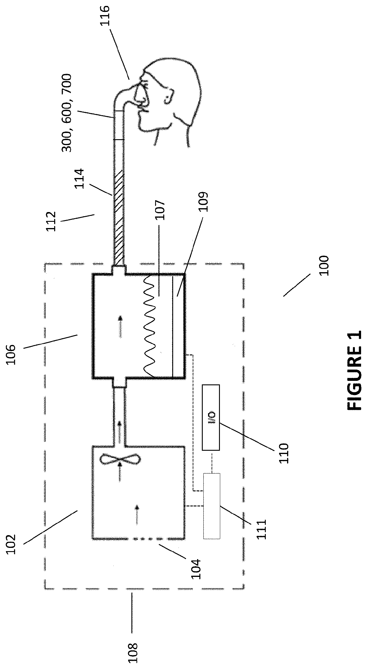
[0015]With reference to the non-limiting exemplary embodiment illustrated in FIG. 1, a respiratory therapy system 100 is shown. The respiratory therapy system 100 comprises a flow generator 102. The flow generator 102 comprises a positive airway pressure or PAP device. The flow generator 102 receives gases from a gases inlet 104 and propels them to a humidifier 106. The flow generator 102 and humidifier 106 may be part of an integrated flow delivery system or may share a housing 108. The humidifier 106 heats and humidifies the gases. The humidifier 106 comprises a quantity of water or another moisturizing agent 107 (hereinafter referred to as water). The humidifier 106 also comprises a heating plate 109 that may be used to heat the water in the humidifier 106 to encourage water vaporization and / or entrainment in the gas flow and increase the temperature of gases passing through the humidifier 106. The heating plate may, for example, comprise a resistive metallic heating plate. Heate...


PUM


Abstract

Various characteristics of a gas flow can be sensed at the end of a respiratory conduit near the patient interface using a sensing module. The sensing module can be removable from the patient end of the respiratory conduit for ease of use and ease of cleaning. The sensor module can transmit sensor data over the same wires used to heat the respiratory conduit.

Description

INCORPORATION BY REFERENCE TO ANY PRIORITY APPLICATIONS[0001]Any and all applications for which a foreign or domestic priority claim is identified in the Application Data Sheet as filed with the present application are hereby incorporated by reference under 37 CFR 1.57.BACKGROUNDTechnical Field[0002]The present disclosure generally relates to sensor modules and control systems for use with gas therapy devices.Description of the Related Art[0003]In patients suffering from obstructive sleep apnea (OSA), muscles that normally keep the upper airway open relax during slumber to the extent that the airway is constrained or completely closed off, a phenomenon often manifesting itself in the form of snoring. When this occurs for a period of time, the patient's brain typically recognizes the threat of hypoxia and partially wakes the patient in order to open the airway so that normal breathing may resume. The patient may be unaware of these waking episodes, which may occur as many as several ...

Claims


Application Information

Patent Timeline
Patent Type & Authority Applications(United States)
IPC IPC(8): A61M16/10A61M16/16A61M16/06A61M16/00
CPCA61M16/161A61M16/109A61M2205/3306A61M16/0069A61M2205/18A61M2230/432A61M16/0875A61M16/06A61M2210/0618A61M2205/3368A61M2205/332A61M16/1095A61M2230/435A61M16/16A61M2016/0027A61M2230/62A61M2016/003A61M2205/3334A61M2205/3375A61M16/0051A61M2205/14A61M2205/42A61M16/026A61M16/0816
Inventor MILLER, JEREMY LIVINGSTONALAMI, NORDYNRHODES, DAVID CHARLES
Owner FISHER & PAYKEL HEALTHCARE LTD
Why Eureka
Try Eureka