Eureka AIR delivers breakthrough ideas for toughest innovation challenges, trusted by R&D personnel around the world.

Compression-ignition internal combustion engine

a technology of compression ignition and internal combustion engine, which is applied in the direction of machines/engines, combustion-air/fuel-air treatment, electric control, etc., can solve the problem of higher temperature of the duct, and achieve the effect of favorable reduction of the wall surface temperature of the flow guide passage, easy maintenance over a long time, and enhanced shape retention of the passage wall portion

Active Publication Date: 2020-01-09
TOYOTA JIDOSHA KK +1
View PDF0 Cites 4 Cited by
  • Summary
  • Abstract
  • Description
  • Claims
  • Application Information

AI Technical Summary

Benefits of technology

The present patent aims to provide a compression-ignition internal combustion engine with a flow guide passage that can enhance the reliability of the passage wall portion and reduce the increase of the wall surface temperature. This is achieved by including a first layer with higher toughness that is connected to the cylinder head, and a second layer with lower thermal conductivity that is located radially outward or inward of the first layer. The first layer maintains the shape of the passage wall portion over a long time, while the second layer prevents the heat transferred from a high-temperature combustion gas from being transferred to the inner wall. In another aspect, the flow guide passage is formed on the top portion of the piston, which includes a first layer with higher toughness that is connected to the piston, and a second layer with lower thermal conductivity that is located under the first layer. This ensures easy maintenance of the shape of the passage wall portion and prevents the heat transferred from a high-temperature combustion gas from being transferred to the walls of the passage wall portion.

Problems solved by technology

Because of this, there is a concern that, as a result of the duct being exposed to a high-temperature combustion gas, the temperature of the duct may become higher.

Method used


Image

  • Compression-ignition internal combustion engine
  • Compression-ignition internal combustion engine
  • Compression-ignition internal combustion engine

Examples


first embodiment

1. First Embodiment

[0035]A first embodiment according to the present disclosure and modification examples thereof will be described with reference to FIGS. 1 to 5.

1-1. Configuration In and Around Combustion Chamber

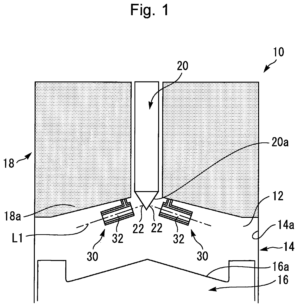
[0036]FIG. 1 is a longitudinal sectional view that schematically illustrates the configuration in and around a combustion chamber 12 of a compression-ignition internal combustion engine (hereunder, simply abbreviated as an “internal combustion engine”) 10 according to the first embodiment of the present disclosure. As an example, the internal combustion engine 10 shown in FIG. 1 is a diesel engine.

[0037]As shown in FIG. 1, the internal combustion engine 10 is provided with a cylinder block 14, pistons 16 and a cylinder head 18. The pistons 16 reciprocate inside the respective cylinders formed in the cylinder block 14. The cylinder head 18 is arranged on the cylinder block 14. The combustion chamber 12 is mainly defined by a cylinder bore surface 14a of the cylinder block 1...

modification examples concerning first embodiment

1-3. Modification Examples Concerning First Embodiment

1-3-1. Another Example of Double-Layered Structure for Duct

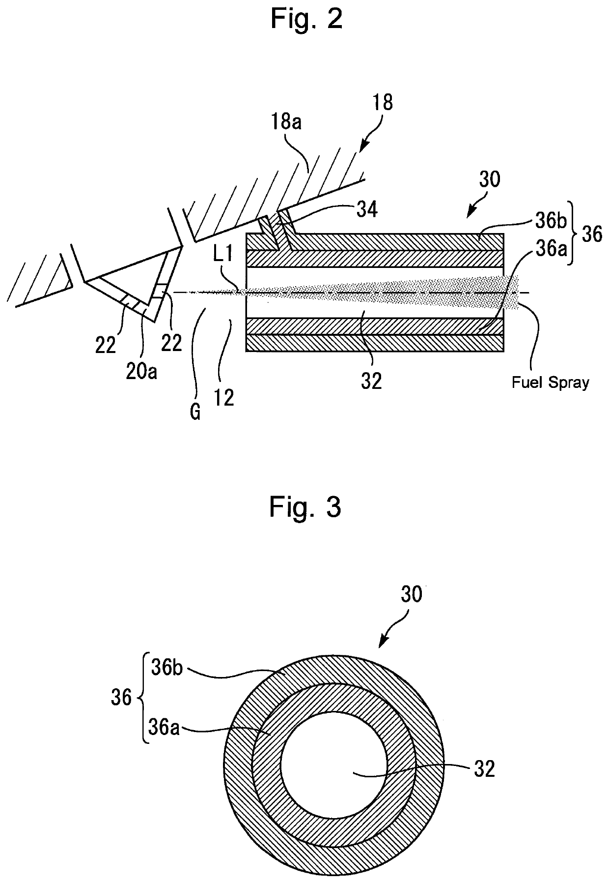
[0056]FIG. 4 is a schematic diagram for describing another example of the configuration of the first and second layers of the passage wall portion. It should be noted that FIG. 4 shows only one of ducts 40, and this also applies to FIGS. 5 to 7. According to the example shown in FIG. 4, a duct 40 (i.e., passage forming member) includes a passage wall portion 42 along with the support portion 34. The passage wall portion 42 includes a first layer 42a and a second layer 42b located radially outward of the first layer 42a.

[0057]According to the example of the duct 30 shown in FIG. 2, the first layer 36a is formed so as to extend over the whole passage wall portion 36 in the longitudinal direction of the flow guide passage 32, and the second layer 36b is formed so as to cover the whole first layer 36a. In contrast to this, according to the example of the duct 40 shown in FIG...

second embodiment

2. Second Embodiment

[0061]Then, a second embodiment according to the present disclosure will be described with reference to FIG. 6.

2-1. Difference from First Embodiment

[0062]FIG. 6 is a schematic diagram for describing the configuration of a duct 60 according to the second embodiment of the present disclosure. An internal combustion engine according to the present embodiment is different, in the following points, from the internal combustion engine 10 according to the first embodiment.

[0063]The duct 60 shown in FIG. 6 includes a passage wall portion 62 along with the support portion 34. The passage wall portion 62 includes a first layer 62a and a second layer 62b. The shape and material of the first layer 62a is the same as those of the first layer 36a shown in FIG. 2. On the other hand, the second layer 62b has the same shape as the second layer 36b shown in FIG. 2 but the second layer 62b and the second layer 36b are different in material as described below.

[0064]More specifically...


PUM


Abstract

A compression-ignition internal combustion engine includes a fuel injection nozzle including a tip end portion exposed in a combustion chamber and a nozzle hole formed at the tip end portion; and a passage forming member forming a flow guide passage through which fuel injected from the nozzle hole passes. The passage forming member includes a passage wall portion located radially outward of the flow guide passage. The passage wall portion includes a first layer that is a base portion connected to a cylinder head, and a second layer located radially outward or radially inward of the first layer. The toughness of the first layer is higher than the toughness of the second layer. The thermal conductivity of the second layer is lower than the thermal conductivity of the first layer.

Description

CROSS-REFERENCE TO RELATED APPLICATION[0001]This application is based on and claims the benefit of Japanese Patent Application No. 2018-129991, filed on Jul. 9, 2018, which is incorporated by reference herein in its entirety.BACKGROUNDTechnical Field[0002]The present disclosure relates to a compression-ignition internal combustion engine.Background Art[0003]For example, US 2016 / 0097360 A1 discloses a technique for controlling a compression-ignition internal combustion engine to promote premixing of fuel and charged air in a combustion chamber of the engine.[0004]According to the technique described above, a duct configured by a hollow pipe is arranged in the vicinity of an opening (i.e., nozzle hole) of a tip end portion of a fuel injection device that is exposed in the combustion chamber. The fuel that is injected from the opening passes through this duct and is injected into the combustion chamber from the duct.SUMMARY[0005]The duct of the compression-ignition internal combustion ...

Claims


Application Information

Patent Timeline
Patent Type & Authority Applications(United States)
IPC IPC(8): F02B77/02F02M61/18F02D41/30
CPCF02B77/02F02M61/1806F05C2251/04F02D41/3035F02M29/04F02B23/0651F02B23/0654F02M61/18F02B23/0672F02B3/06F02B23/02F02F3/28F02M61/14F02M55/00
Inventor TANNO, SHIROKAWAE, TSUTOMU
Owner TOYOTA JIDOSHA KK
Why Eureka
Eureka Blog
Learn More