
A slurry drying plant, a method for drying slurry and use of a slurry drying plant

Active Publication Date: 2019-12-12
AQUAGREEN LICENSE APS +1
View PDF0 Cites 2 Cited by
  • Summary
  • Abstract
  • Description
  • Claims
  • Application Information

AI Technical Summary

Benefits of technology

The patent text describes using screw conveyors to create a mesh to increase heat transfer and improve slurry distribution for faster and more efficient drying. It also suggests that the conveyors should be almost touching to ensure optimal performance. Additionally, the text suggests that the solid matter content in the slurry should be at least a certain level to ensure proper viscosity and handling.

Problems solved by technology

Organic slurry such as slurry from sewage treatment, farming, aquaculture, biochemical production, food production or other is problematic in that it is difficult and expensive to handle, store and dispose, it can contain drug residues, virus or other and it can emit bad smells or environmentally damaging gasses such as ammonium.
But such a dryer design is expensive to manufacture and run.

Method used


Image

  • A slurry drying plant, a method for drying slurry and use of a slurry drying plant
  • A slurry drying plant, a method for drying slurry and use of a slurry drying plant

Examples


Embodiment Construction

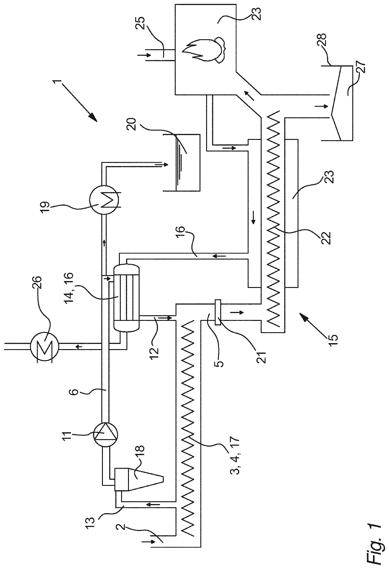
[0059]FIG. 1 illustrates an embodiment of a slurry drying plant 1, as seen from the side.

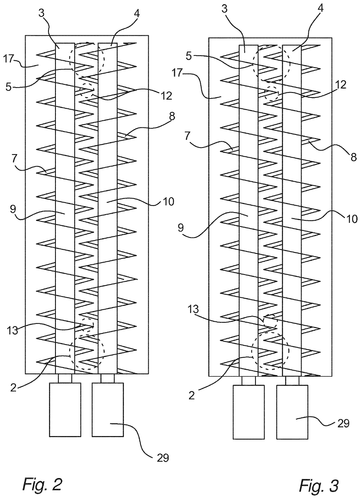
[0060]In this embodiment of the invention slurry drying plant 1 comprises two meshing screw conveyors 3, 4 arranged in a screw conveyer chamber 17 as will be discussed in more details in relation with FIGS. 2 and 3. The screw conveyer chamber 17 further comprises a slurry inlet 2 arranged at one end of the chamber 17 and a slurry outlet 5 arranged at the opposite end of the chamber 17.

[0061]The slurry drying plant 1 further comprises slurry heating means 6 arranged to pass superheated steam past slurry and the two meshing screw conveyors 3, 4 while they are conveying the slurry. In this embodiment the slurry heating means 6 is arranged to circulate steam through a steam inlet 12, along through the screw conveyer chamber 17, out through a steam outlet 12, through a cyclone device 18, through flow means 11, through steam heating means 14 and out through the steam inlet 12 again. I.e. in this embod...


PUM


Abstract

Disclosed is a slurry drying plant (1) comprising a slurry inlet (2) for feeding slurry to the slurry drying plant (1) and two or more meshing screw conveyors (3, 4) arranged to at least partly divide the slurry while conveying the slurry in a transport direction from the slurry inlet (2) to a slurry outlet (5). The slurry drying plant (1) further includes slurry heating means (6) comprising means for passing superheated steam substantially at atmospheric pressure past the slurry and the two or more meshing screw conveyors (3, 4), while they are conveying the slurry. Furthermore, a method for drying slurry and use of a slurry drying plant (1) is disclosed.

Description

FIELD OF THE INVENTION[0001]The invention relates to a slurry drying plant comprising a slurry inlet for feeding slurry to the slurry drying plant. The invention further relates to a method for drying slurry and use of a slurry drying plant.BACKGROUND OF THE INVENTION[0002]Organic slurry such as slurry from sewage treatment, farming, aquaculture, biochemical production, food production or other is problematic in that it is difficult and expensive to handle, store and dispose, it can contain drug residues, virus or other and it can emit bad smells or environmentally damaging gasses such as ammonium.[0003]A solution would be to dry the slurry to reduce or even substantially removed the water content of the slurry to reduce or even completely eliminate the abovementioned problems.[0004]Thus, from the US patent application US 2014 / 0190792 A1 a dryer for drying sludge by means of two screw conveyers formed by a number of blades is known. Superheated steam is guided through the hollow sha...

Claims


Application Information

Patent Timeline
IPC IPC(8): F26B3/06F26B17/20
CPCF26B3/06B65G33/18B65G33/30F26B2200/18F26B23/02F26B21/005F26B17/20
Inventor AHRENFELDT, JESPERHENRIKSEN, ULRIK BIRKTHULSTRUP, CLAUS
Owner AQUAGREEN LICENSE APS
Learn More