
Casting method

a casting method and casting technology, applied in the direction of coil arrangement, induction heating, electrical equipment, etc., can solve the problems of limiting the quantity of material that can be melted in this manner, unable to teach that molten charge is sufficient for filling the mold, and the levitation melting has not been established in practice, so as to avoid material loss and high throughput

Active Publication Date: 2019-12-05
ALD VACUUM TECH GMBH
View PDF3 Cites 5 Cited by
  • Summary
  • Abstract
  • Description
  • Claims
  • Application Information

AI Technical Summary

Benefits of technology

The invention provides a method for using levitation melting in industrial applications without the material loss typically associated with other methods. The method allows for high throughput and the ability to melt a large amount of material without the need for a supporting platform, resulting in high-quality cast items. These technical effects enable the industrial use of levitation melting technology.

Problems solved by technology

However, this document does not teach that a molten charge is sufficient for filling the mould.
It is already known that the “weak spot” of coil arrangements of this kind is at the centre of the coils, which limits the quantity of material that can be melted in this manner.
And yet, levitation melting has not become established in practice.
However, material melted in this manner proves difficult to pour into a mould.
Furthermore, this process produces a significant proportion of unusable material which has been contaminated by contact with the platform.
Full-levitation melting methods can be used only with small quantities of material, and so industrial application has not been successful hitherto.
Semi-levitating melting methods have the drawback of it being necessary to discard that proportion of the material used which has come into contact with the platform.
Also, pouring into moulds is difficult.
As a result, it has hitherto not been possible to carry out full-levitation melting methods for the production of cast items on an industrial scale.

Method used


Image

  • Casting method
  • Casting method
  • Casting method

Examples


Embodiment Construction

[0017]In one embodiment, the method comprises the step of removing the filled mould from the filling region after pouring but prior to removal of the solidified cast item. This embodiment is employed to particular advantage when using lost moulds, since it frees up the filling region for another lost mould. In another embodiment, in particular when using a permanent mould, the removal of the cast item can take place in the filling region.

[0018]The solidified cast item can be removed in various ways. In one embodiment, the mould is destroyed when removing the cast item. This is referred to as the “lost mould” method. In another embodiment, the mould can be made as a permanent mould, in particular as a permanent die. Permanent dies are preferably made of a metallic material. They are suitable for simpler components.

[0019]A permanent mould preferably has two or more mould elements that can be separated from one another in order to remove the cast item. One or more ejectors can be used ...


PUM

PropertyMeasurementUnit
pressureaaaaaaaaaa
melting pointaaaaaaaaaa
temperatureaaaaaaaaaa

Abstract

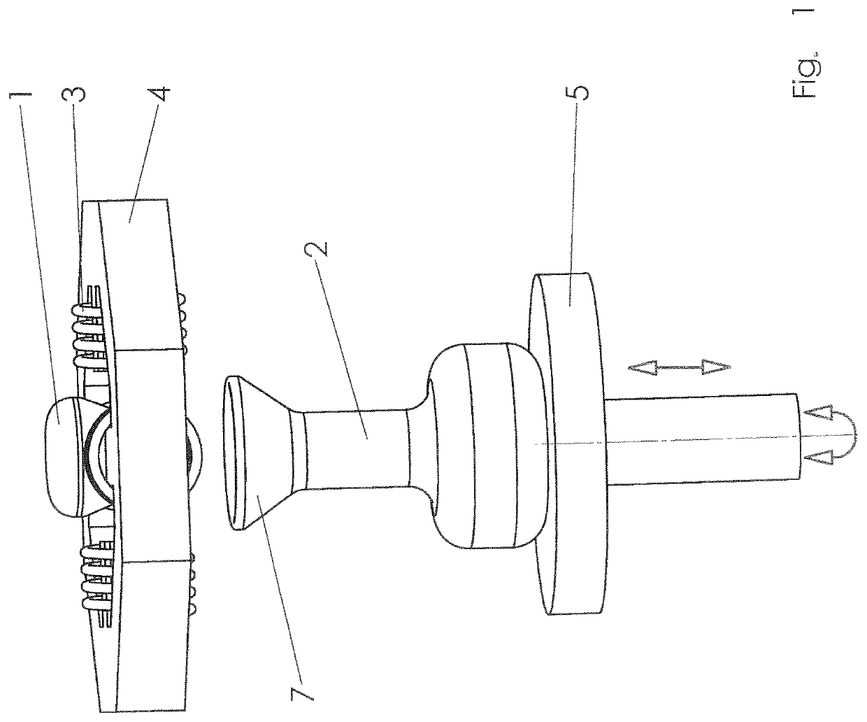
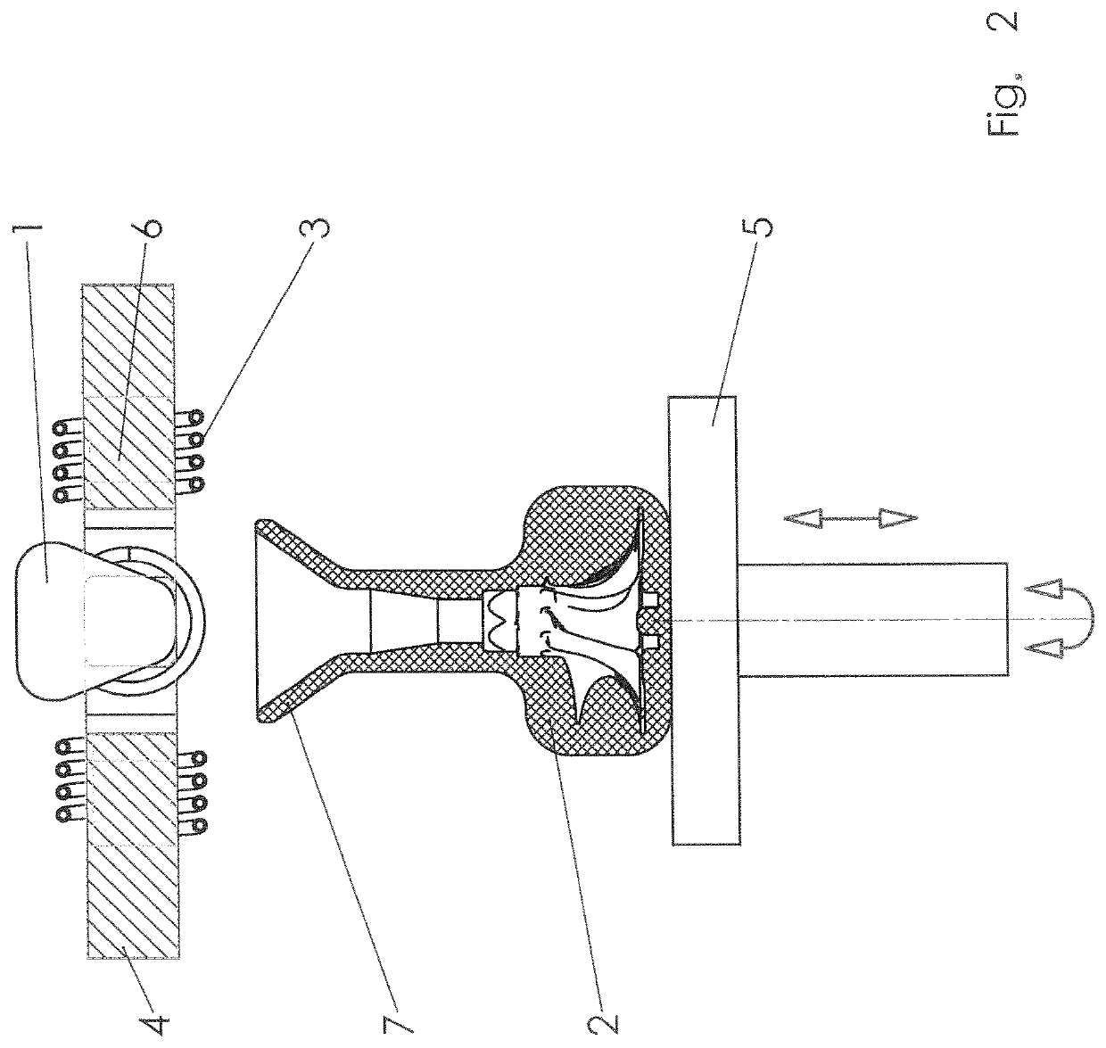
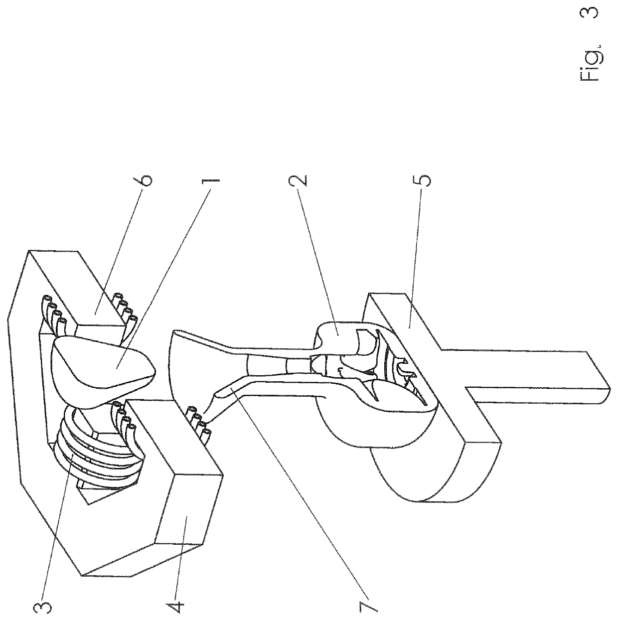
A method for producing cast items in a casting method, wherein a charge of a conductive material is introduced into the sphere of influence of at least one alternating electromagnetic field, so that the charge is kept in a levitating state. The melt is poured into moulds in order to produce turbine blades, prostheses or turbocharger impellers.

Description

FIELD OF THE INVENTION[0001]This invention relates to a casting method for producing cast items. The method is a levitation melting method in which the melt does not come into contact with the material of a crucible, thus making it possible to avoid contamination with the crucible material or by a reaction between the melt and the crucible material.[0002]Avoiding this kind of contamination is important especially in the case of metals and alloys having high melting points. Such metals are for example titanium, zirconium, vanadium, tantalum, tungsten, hafnium, niobium, rhenium and molybdenum. However, it is also important in the case of other metals and alloys such as nickel, iron and aluminium.BACKGROUND OF THE INVENTION[0003]Levitation melting methods are known from the prior art. Thus, a melting method in which the conductive melt material is heated by means of inductive currents and is simultaneously made to float freely by means of electrodynamic effects is already disclosed in ...

Claims


Application Information

Patent Timeline
Patent Type & Authority Applications(United States)
IPC IPC(8): B22D39/00B22D13/10B22D13/02B22D21/02B22D27/15B22D27/00
CPCB22D13/107B22D27/003B22D13/026B22D21/022B22D27/15B22D39/003B22D21/025B22D13/12B22D21/02H05B6/32H05B6/44H05B6/365B22D18/06B22D39/00
Inventor FRANZ, HENRIKSPITANS, SERGEJSBETZ, ULRICHBAUER, EGONHOLZ, MARKUS
Owner ALD VACUUM TECH GMBH
Learn More