Electronic component with shield plate and shield plate of electronic component
a technology of electronic components and shield plates, applied in the direction of shielding materials, cross-talk/noise/interference reduction, non-metallic protective coating applications, etc., can solve the problem that the flexibility of magnetic ceramic sintered sheets is inferior to that of composite members or mesh members, and achieves the effect of reducing unwanted stress, small thickness, and small thickness
- Summary
- Abstract
- Description
- Claims
- Application Information
AI Technical Summary
Benefits of technology
Problems solved by technology
Method used
Image
Examples
first preferred embodiment
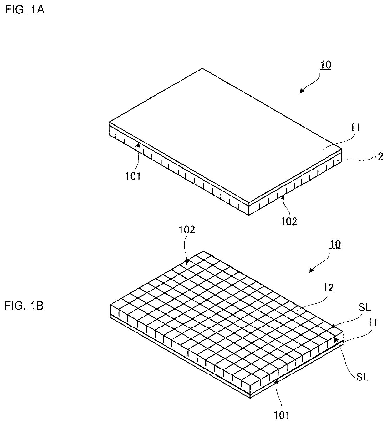
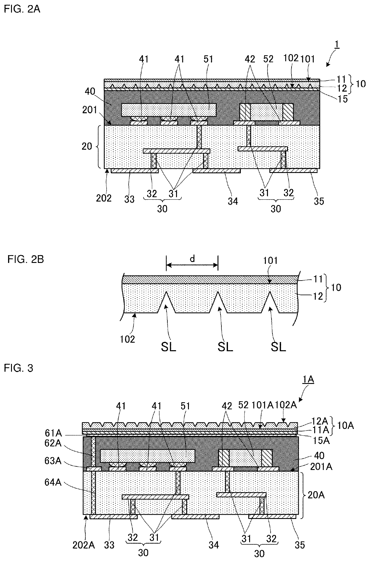
[0045]An electronic component with a shield plate according to a first preferred embodiment of the present invention will be described below with reference to the drawings. FIG. 1A is an external perspective view of a shield plate of an electronic component according to the first preferred embodiment of the present invention, as viewed from the side of a first main surface. FIG. 1B is an external perspective view of the shield plate according to the first preferred embodiment of the present invention, as viewed from the side of a second main surface. FIG. 2A is a side sectional view illustrating the configuration of the electronic component according to the first preferred embodiment of the present invention. FIG. 2B is an enlarged view of a portion of the shield plate shown in FIG. 2A. For the sake of easy representation, some reference numerals are not shown in FIG. 1A and 1B.
[0046]As shown in FIGS. 1A and 1B, a shield plate 10 preferably includes a metal film 11 and a magnetic ce...
second preferred embodiment
[0059]An electronic component with a shield plate according to a second preferred embodiment of the present invention will be described below with reference to the drawing. FIG. 3 is a side sectional view illustrating the configuration of the electronic component according to the second preferred embodiment of the present invention.
[0060]As shown in FIG. 3, an electronic component 1A with a shield plate according to the second preferred embodiment is different from the electronic component 1 according to the first preferred embodiment in that via-hole conductors 62A and 64A and a terminal conductor 63A are provided and the shape of a shield plate 10A of an electronic component is different. The shield plate 10A preferably includes a metal film 11A and a magnetic ceramic sintered sheet 12A. The configurations of the other elements of the electronic component 1A are preferably the same as or similar to those of the electronic component 1 and will not be explained. The metal film 11A c...
third preferred embodiment
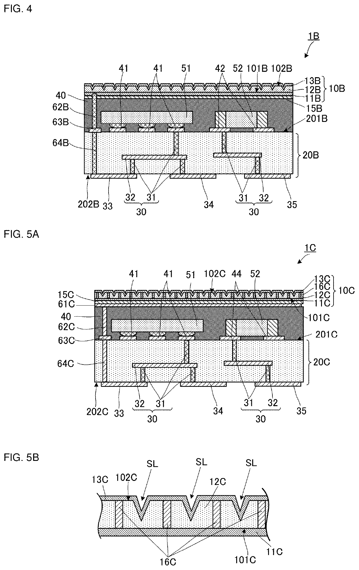
[0068]An electronic component with a shield plate according to a third preferred embodiment of the present invention will be described below with reference to the drawing. FIG. 4 is a side sectional view illustrating the configuration of the electronic component according to the third preferred embodiment of the present invention.
[0069]As shown in FIG. 4, an electronic component 1B with a shield plate according to the third preferred embodiment is different from the electronic component 1 according to the first preferred embodiment in that a metal post 62B, a terminal conductor 63B, and a via-hole conductor 64B are provided and the shapes of a shield plate 10B of an electronic component and a magnetic ceramic sintered sheet 12B are different. The configurations of the other elements of the electronic component 1B are preferably the same as or similar to those of the electronic component 1 and will not be explained. A metal film 11B corresponds to the metal film 11 of the first prefe...
PUM
| Property | Measurement | Unit |
|---|---|---|
| total thickness | aaaaa | aaaaa |
| frequencies | aaaaa | aaaaa |
| distance | aaaaa | aaaaa |
Abstract
Description
Claims
Application Information
 - R&D
- Intellectual Property
- Life Sciences
- Materials
- Tech Scout
- Unparalleled Data Quality
- Higher Quality Content
- 60% Fewer Hallucinations
Browse by: Latest US Patents, China's latest patents, Technical Efficacy Thesaurus, Application Domain, Technology Topic, Popular Technical Reports.
© 2025 PatSnap. All rights reserved.Legal|Privacy policy|Modern Slavery Act Transparency Statement|Sitemap|About US| Contact US: help@patsnap.com


