
Inductive sensing system for sensing electromagnetic signals from a body

a sensing system and electromagnetic technology, applied in medical science, diagnostics, auscultation instruments, etc., can solve the problems of inability to adopt a technology, inability to achieve inductive sensors, and inability to achieve electromagnetic signals, so as to reduce energy consumption and required computing power, save power, and reduce power.

Active Publication Date: 2019-11-07
KONINKLJIJKE PHILIPS NV
View PDF0 Cites 2 Cited by
  • Summary
  • Abstract
  • Description
  • Claims
  • Application Information

AI Technical Summary

Benefits of technology

The patent text describes a new technique for improving the sensitivity of electromagnetic sensors by reducing the signal to noise ratio. This is achieved by exciting the body with high-frequency signals. This technique was previously thought to be ineffective due to the limitations of frequency range and required power. However, the inventors found that this reduction in penetration depth does not negatively impact the signal strength, especially for physiological parameter sensing such as breathing function. Thus, the technique improves the strength of the sensed signal without restricting the depth of penetration.

Problems solved by technology

The ongoing research however has never led to adoption of the technology in commercial applications, since the signals achieved from inductive sensors remain notoriously weak, and often saturated by noise.
In state of the art systems, signal strength remains prohibitively low, preventing the technology from being usefully applied in commercial applications.

Method used


Image

  • Inductive sensing system for sensing electromagnetic signals from a body
  • Inductive sensing system for sensing electromagnetic signals from a body
  • Inductive sensing system for sensing electromagnetic signals from a body

Examples


Embodiment Construction

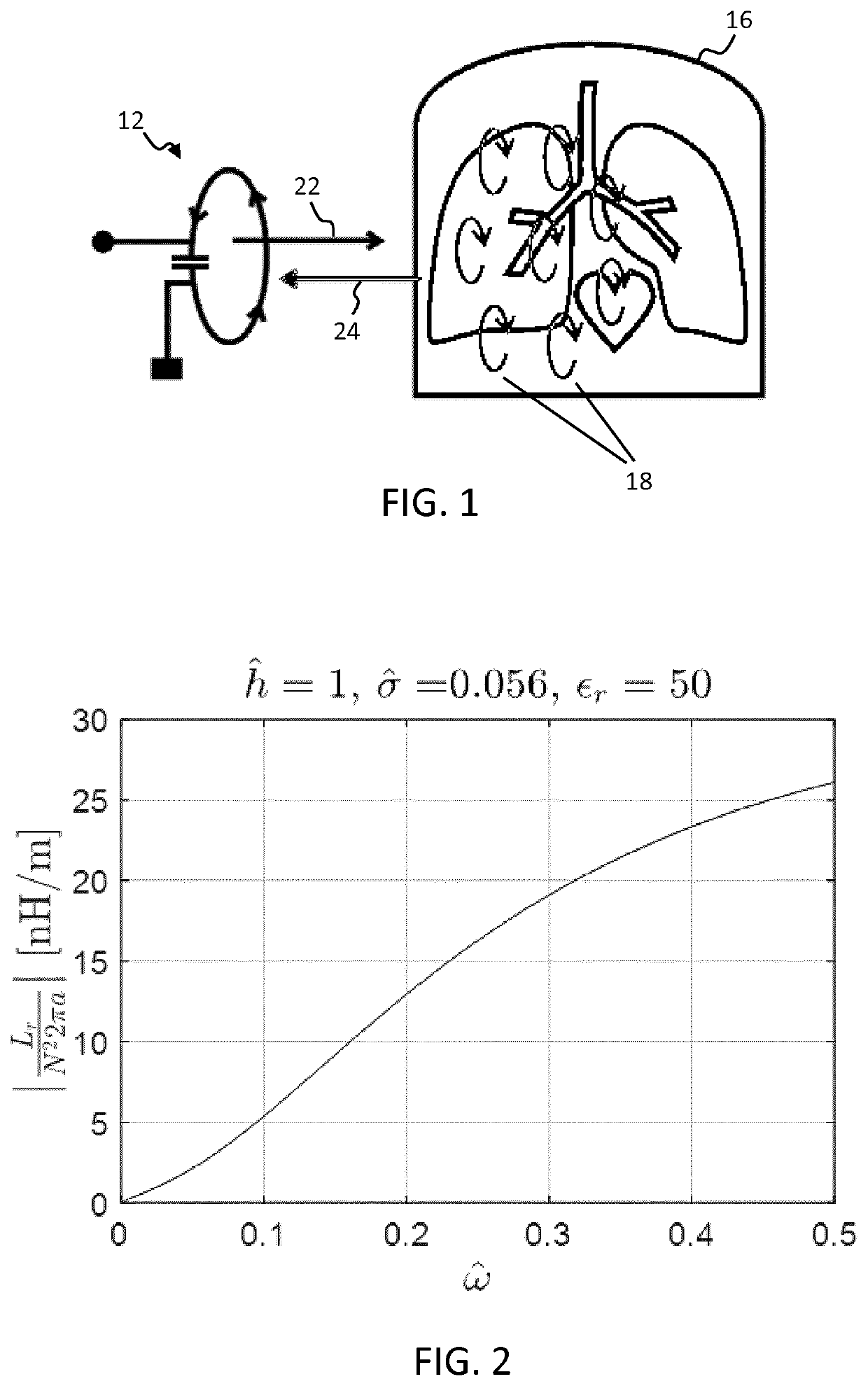
[0107]The invention provides a magnetic inductive sensing system for sensing electromagnetic signals emitted from a body in response to electromagnetic excitation signals applied to the body. The electromagnetic signals are generated and sensed by the same loop resonator which comprises a single-turn loop antenna and a tuning capacitor. The loop antenna of the resonator and a signal generation means for exciting the resonator to generate excitation signals are together configured so as to optimize the value of a ratio between the radial frequency of the generated electromagnetic excitation signals and a reference frequency of the antenna, where the reference frequency is the frequency for which one wavelength of the generated excitation signals (waves) matches the circumferential length of the antenna. This ratio, which corresponds to a normalized radial frequency of the generated excitation signals, is maintained between a value of 0.025 and 0.50.

[0108]The invention is based on res...


PUM


Abstract

The invention provides a magnetic inductive sensing system for sensing electromagnetic signals emitted from a body in response to electromagnetic excitation signals applied to the body. The electromagnetic signals are generated and sensed by the same loop resonator which comprises a single-turn loop antenna and a tuning capacitor. The loop antenna of the resonator and a signal generation means for exciting the resonator to generate excitation signals are together configured so as to optimize the value of a ratio between the radial frequency of the generated electromagnetic excitation signals and a reference frequency of the antenna, where the reference frequency is the frequency for which one wavelength of the generated excitation signals (waves) matches the circumferential length of the antenna. This ratio, which corresponds to a normalized radial frequency of the generated excitation signals, is maintained between a value of 0.025 and 0.50.

Description

FIELD OF THE INVENTION[0001]This invention relates to an inductive sensing system for sensing electromagnetic signals from a body, and in particular a sensor for inductively coupling with a body for sensing electromagnetic signals.BACKGROUND OF THE INVENTION[0002]Inductive sensing can be used as a means of non-invasive investigation of properties of a body.[0003]In one advantageous area of application, inductive sensing can be used as a means of non-invasively investigating physiological characteristics, in particular heart and lung dynamics. Inductive sensing is based on magnetic induction and has several advantages over conductive and capacitive sensing.[0004]An advantage compared to conductive sensing, such as bio-impedance measurements, is that adhesive electrodes are not required; sensing may be performed without contact and / or through non-conductive material, such as textile and plastic.[0005]An advantage compared with capacitive sensing is that inductive sensing is based on m...

Claims


Application Information

Patent Timeline
IPC IPC(8): A61B5/0265A61B5/00
CPCA61B2562/222A61B5/7225A61B5/0265A61B2560/0462A61B2562/166A61B2562/182A61B7/003A61B5/05A61B2562/0223
Inventor PEETERS, WOUTER HERMANKLEIJNEN, MARK PETER PAULDOODEMAN, GERARDUS JOHANNES NICOLAASBEZEMER, RICKLEIJSSEN, JACOBUS JOSEPHUSGROSFELD, RONNY HUBERTUS JOHANNES
Owner KONINKLJIJKE PHILIPS NV
Learn More