
Micro-Grid Luminescent Solar Concentrators and Related Methods of Manufacturing

a luminescent solar concentrator and micro-grid technology, applied in the direction of luminescent compositions, semiconductor devices, chemistry apparatus and processes, etc., can solve the problems of limiting the dissemination of solar power into the global energy market, unable to use collected light, and economic inferiority of si-pv technology to fossil fuels

Inactive Publication Date: 2019-10-24
CALIFORNIA INST OF TECH +2
View PDF2 Cites 8 Cited by
  • Summary
  • Abstract
  • Description
  • Claims
  • Application Information

AI Technical Summary

Benefits of technology

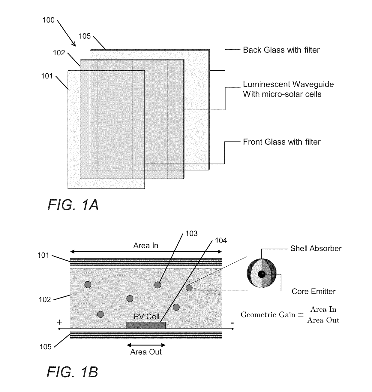
The present invention is related to a luminescent solar concentrator that includes a waveguide layer, a plurality of luminophores, and a plurality of photovoltaic cells. The luminophores absorb incident light and emit infrared light within the waveguide layer, while the photovoltaic cells convert the incident light into a voltage signal. The photovoltaic cells are interconnected in a grid pattern. The invention has several technical effects, such as high conversion efficiency, high transparency, and the ability to capture a wide range of wavelengths of light. Additionally, the invention includes a first filter component and a second filter component to improve the quality of the light captured by the concentrator.

Problems solved by technology

Despite recent LCOE reductions, Si-PV technology remains economically inferior to fossil fuels.
Both the strict DNI requirement and the high LCOE of Si-PV cells ultimately limit the dissemination of solar power into the global energy market.
However, some of the gathered light may not be useable due to losses from absorption and escaped light and, as is the case with geometric concentrators, light that occupies angles outside the acceptance angle.
However, LSCs have not yet reached commercialization for photovoltaic power generation, largely due to their comparatively low power conversion efficiencies (PCEs) and lack of scalability.

Method used


Image

  • Micro-Grid Luminescent Solar Concentrators and Related Methods of Manufacturing
  • Micro-Grid Luminescent Solar Concentrators and Related Methods of Manufacturing
  • Micro-Grid Luminescent Solar Concentrators and Related Methods of Manufacturing

Examples


Embodiment Construction

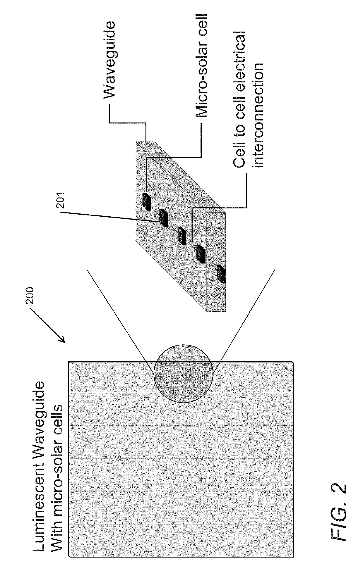
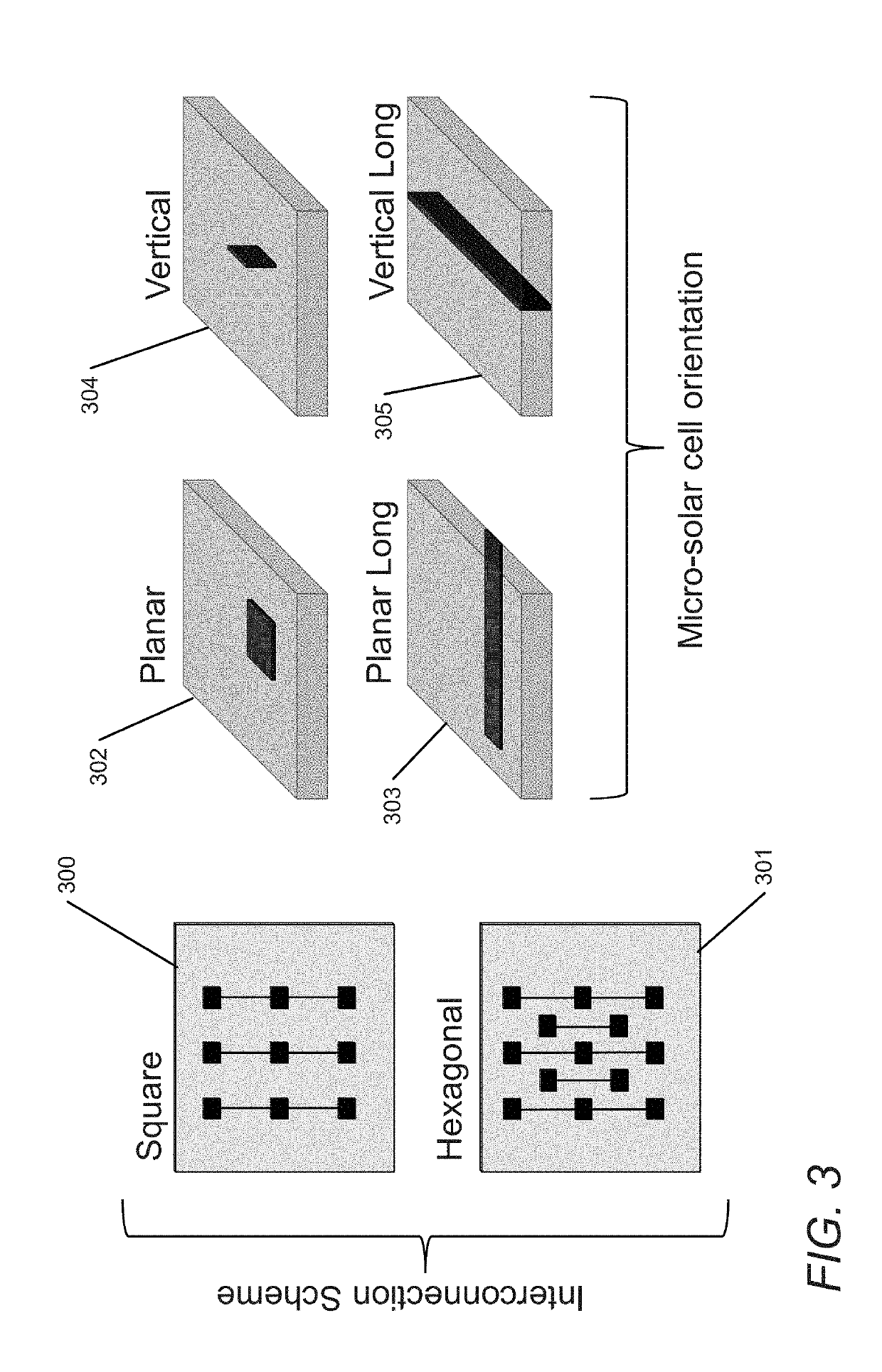
[0035]Luminescent solar concentrators in accordance with various embodiments of the invention can be utilized for many different applications, including but not limited to transparent and semi-transparent photovoltaic applications. For example, an LSC can be implemented in a solar power window capable of harvesting light for energy conversion. Current state-of-the-art luminescent solar concentrators manufactured for power window markets orient the PV component as an edge-lining structure. In such structures, increasing window area results in an increase in average light travel lengths, which reduces the power conversion efficiencies (PCEs) of the window. LSCs in accordance with various embodiments of the invention can be configured to maintain constant light travel lengths within the waveguide by employing a grid of PV cells that are separated by a certain distance, which can also be termed as the geometric gain. Utilizing such structures, the window area can be scalable without an ...


PUM


Abstract

Luminescent solar concentrators having a grid-based PV design can be implemented in many different ways. In several embodiments, the LSC is implemented using infrared luminophore technology combined with a PV design implementing a grid of PV cells. LSCs can incorporate quantum dots that absorb uniformly across the visible spectrum and photoluminesce down-shifted energy light in the infrared wavelength regime. Some embodiments include PV cells utilizing micro-grid structures that can be implemented for scalable and controllably transparent applications, such as but not limited to power windows targeted for building integrated photovoltaic applications. In a number of embodiments, the LSCs can utilize a unique PV cell form factor and spectral filter coatings to increase the thermal insulation of the window and enhance photocurrent capture by a silicon micro-grid.

Description

CROSS-REFERENCE TO RELATED APPLICATIONS[0001]The current application claims the benefit of and priority under 35 U.S.C. § 119(e) to U.S. Provisional Patent Application No. 62 / 660,455 entitled “Luminescent Solar Concentrator Micro-Grid Power Window,” filed Apr. 20, 2018. The disclosure of U.S. Provisional Patent Application No. 62 / 660,455 is hereby incorporated by reference in its entirety for all purposes.FIELD OF THE INVENTION[0002]The present invention generally relates to luminescent solar concentrators and, more specifically, to micro-grid luminescent solar concentrators.BACKGROUND[0003]Silicon photovoltaic (Si-PV) modules currently dominate the solar energy market. Increased progress into Si-PV efficiency enhancements combined with historically low module costs aim to decrease the overall Levelized Cost of Electricity (LCOE) to a point competitive with non-renewable energy sources. Despite recent LCOE reductions, Si-PV technology remains economically inferior to fossil fuels. A...

Claims


Application Information

Patent Timeline
IPC IPC(8): H01L31/055H01L31/054H01L31/0475H01L31/0216
CPCH01L31/02162H01L31/0543H01L31/0475H01L31/055H01L31/0547H01L31/042H01L31/0481C09K11/025C09K11/7492C09K11/70C09K11/88C09K11/565C09K11/621Y02E10/52
Inventor NEEDELL, DAVID R.BAUSER, HALEYATWATER, HARRY A.ALIVISATOS, ARMAND P.NUZZO, RALPHILIC, OGNJENBUKOWSKY, COLTONKOSCHER, BRENT A.PHELAN, MEGAN
Owner CALIFORNIA INST OF TECH
Learn More