
System and method for laser beveling and/or polishing

Active Publication Date: 2019-10-17
IPG PHOTONICS CORP
View PDF0 Cites 4 Cited by
  • Summary
  • Abstract
  • Description
  • Claims
  • Application Information

AI Technical Summary

Benefits of technology

The patent describes a method and system for processing edges of a part using a laser beam that is directed at the edge of the part with an angle of incidence greater than 0° and less than a critical angle. The laser system includes a motion stage for supporting the part and moving it in multiple axes relative to the angled laser beam. The control system coordinates the motion of the part in order to achieve precise processing of the edge defects. The technical effect of this method and system is that it allows for improved quality and efficiency in part processing, particularly in applications where edge defects need to be reduced or eliminated.

Problems solved by technology

Conventional mechanical methods for treating or processing sapphire and other such materials include diamond scribing and blade dicing; however, these methods often lead to breaking the substrate, which lowers production yields.
Certain materials, however, present challenges when processing using lasers.
The existing techniques used for laser processing of sapphire discussed above also suffer from other drawbacks.
In particular, the cost of pulsed lasers is high and the multi-step process of forming cracks and separating parts is time consuming and cost inefficient.
Also, the wavelengths used in UV cutting require the use of crystals, which may have a short useful life and may present issues with the maintenance of these lasers.
Cutting hard dielectric materials also presents challenges because of the defects and imperfections that might form in the material after cutting.
Hard dielectric materials including crystalline and amorphous ceramics have a tendency to fail in tension before they fail in compression.
Stress concentrations at the cut edges, for example, may lead to crack propagation throughout the material.
These materials may be more susceptible to these defects and imperfections when certain types of lasers are used to perform the cutting.
Sometimes the lasers that perform the cutting most efficiently (e.g., at a lower cost and higher speeds) may cause edge defects such as chipping, cracking, and induced stress concentrations proximate the cut edges.

Method used


Image

  • System and method for laser beveling and/or polishing
  • System and method for laser beveling and/or polishing
  • System and method for laser beveling and/or polishing

Examples


Embodiment Construction

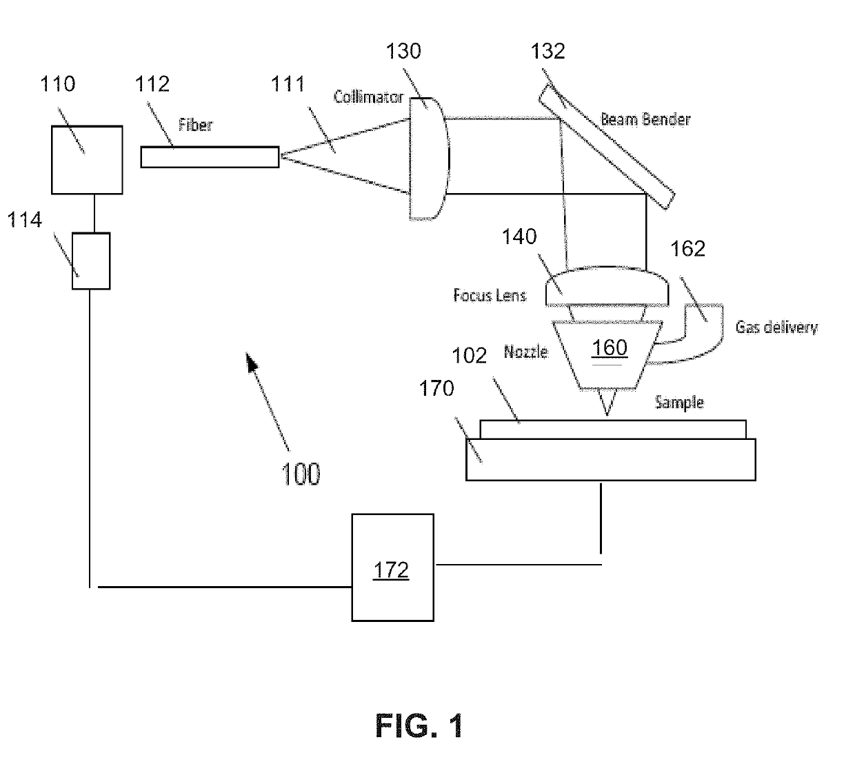
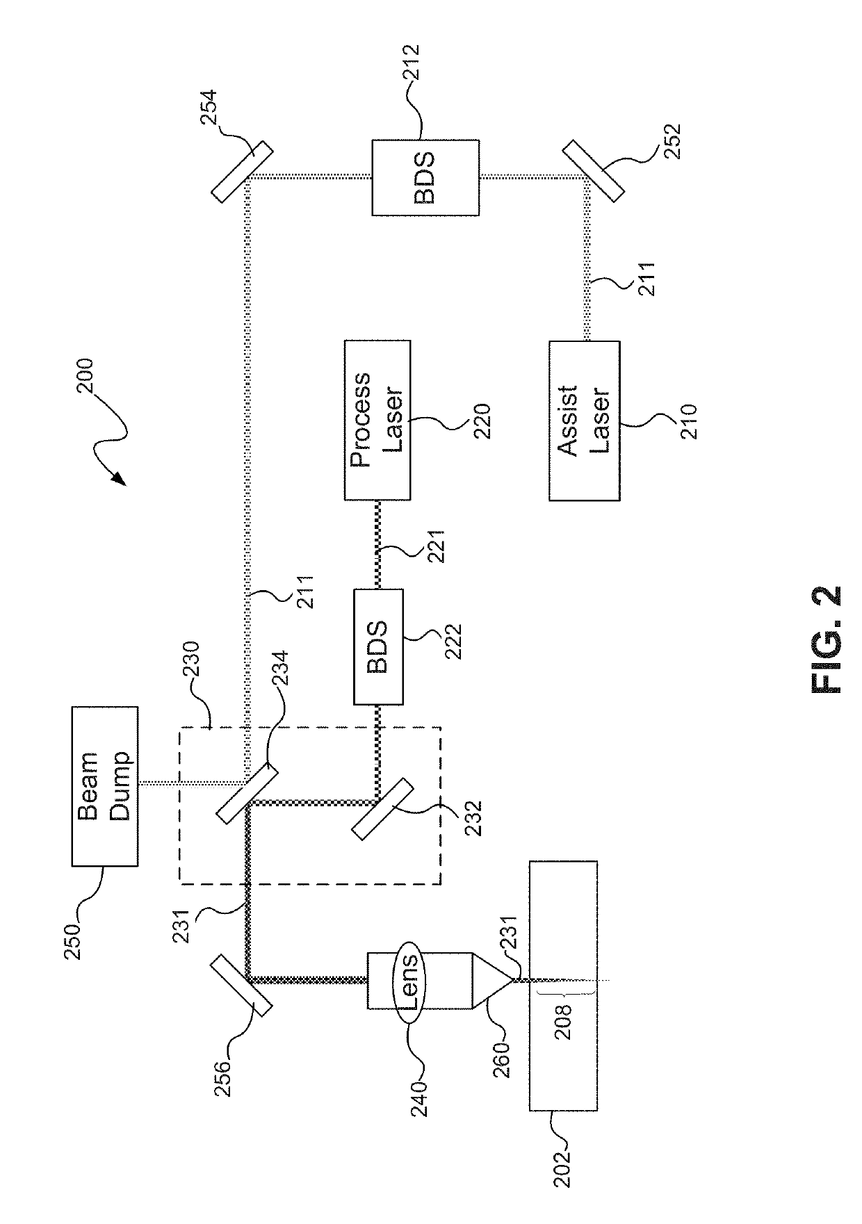
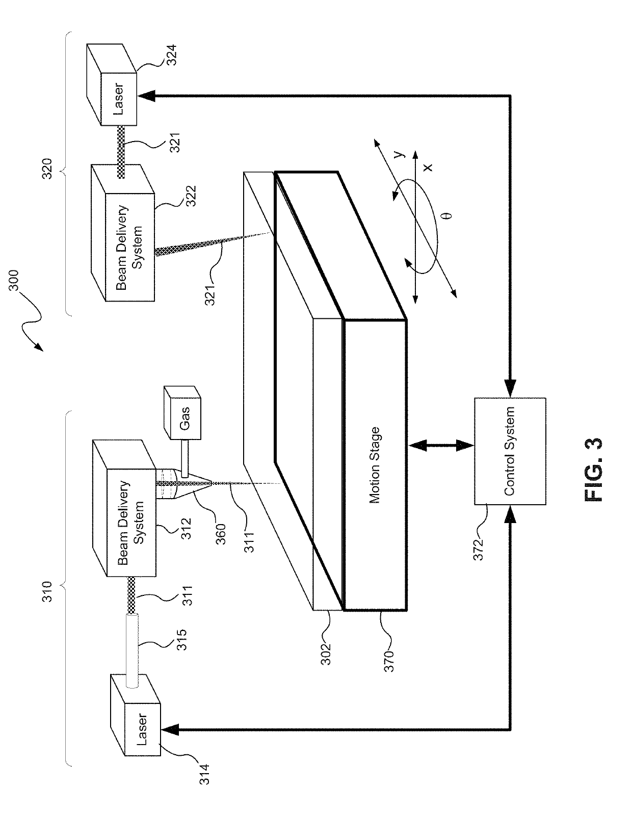
[0030]Laser processing of hard dielectric materials, consistent with embodiments of the present disclosure, may include cutting a part from a hard dielectric material using a continuous wave laser operating in a quasi-continuous wave (QCW) mode to emit consecutive laser light pulses in a wavelength range of about 1060 nm to 1070 nm (hereinafter “QCW laser”). Cutting using a QCW laser may be performed with a lower duty cycle (e.g., between about 1% and 15%) and in an inert gas atmosphere such as nitrogen, argon or helium. Laser processing of hard dielectric materials may further include post-cut processing the cut edges of the part cut from the dielectric material, for example, by beveling and / or polishing the edges to reduce edge defects. The post-cut processing may be performed using a laser beam with different laser parameters than the beam used for cutting, for example, by using a shorter wavelength (e.g., 193 nm excimer laser) and / or a shorter pulse width (e.g., a picosecond las...


PUM

PropertyMeasurementUnit
Angleaaaaaaaaaa
Fractionaaaaaaaaaa
Fractionaaaaaaaaaa

Abstract

Laser processing of hard dielectric materials may include cutting a part from a hard dielectric material using a continuous wave laser operating in a quasi-continuous wave (QCW) mode to emit consecutive laser light pulses in a wavelength range of about 1060 nm to 1070 nm. Cutting using a QCW laser may be performed with a lower duty cycle (e.g., between about 1% and 15%) and in an inert gas atmosphere such as nitrogen, argon or helium. Laser processing of hard dielectric materials may further include post-cut processing the cut edges of the part cut from the dielectric material, for example, by beveling and / or polishing the edges to reduce edge defects. The post-cut processing may be performed using a laser beam with different laser parameters than the beam used for cutting, for example, by using a shorter wavelength (e.g., 193 nm excimer laser) and / or a shorter pulse width (e.g., picosecond laser).

Description

CROSS-REFERENCE TO RELATED APPLICATIONS[0001]The present application is a divisional of U.S. patent application Ser. No. 14 / 838,837 filed Aug. 28, 2015, which claims the benefit of U.S. Provisional Patent Application Ser. No. 62 / 043,367 filed Aug. 28, 2014, which is fully incorporated herein by reference. The present application is also related to International Application No. PCT / US14 / 19460 filed Feb. 28, 2014 (Attorney Docket No. IPGP004PCT) entitled LASER SYSTEM AND METHOD OF USING SAME FOR PROCESSING SAPPHIRE and U.S. Provisional Patent Application Ser. No. 61 / 945,911 filed Feb. 28, 2014 (Attorney Docket No. IPGM006P) entitled MULTIPLE-BEAM LASER PROCESSING USING MULTIPLE LASER BEAMS WITH DISTINCT WAVELENGTHS AND / OR PULSE DURATIONS, both of which are fully incorporated herein by reference.BACKGROUND OF THE DISCLOSUREField of the Disclosure[0002]The present disclosure relates to processing materials using lasers, and more particularly, relates to a system and method for laser bev...

Claims


Application Information

Patent Timeline
IPC IPC(8): B23K26/361B23K26/38B23K26/402B23K26/08
CPCB23K26/38B23K2103/50B23K2103/52B23K26/402B23K26/361B23K2103/54B23K26/0853B23K2103/56B23K26/0823B23K26/082B23K26/0624B23K26/354B23K26/3576
Inventor SERCEL, JEFFREY P.MENDES, MARCOSARRAFI, ROUZBEHSCHOENLY, JOSHUASONG, XIANGYANGHANNON, MATHEWSOKOL, MIROSLAW
Owner IPG PHOTONICS CORP
Learn More