
Charged particle beam device

a particle beam and charge technology, applied in the direction of electrical discharge tubes, sampling, instruments, etc., can solve the problem of increasing the time required for the entire automatic sampling process

Active Publication Date: 2019-10-03
HITACHI HIGH TECH SCI CORP
View PDF4 Cites 7 Cited by
  • Summary
  • Abstract
  • Description
  • Claims
  • Application Information

AI Technical Summary

Benefits of technology

The patent describes a method of depositing a film onto a needle and then using a charged particle beam to remove any impurities. The method allows for faster and more efficient automatic sampling of a sample piece compared to traditional needle cleaning methods.

Problems solved by technology

However, in the automatic sampling in which the posture of the sample piece is shifted, it is required to perform needle trimming more frequently in order to maintain the connection strength such that the sample piece is not blown away from the needle by the rotation of the needle, and there has been a problem in that time required for the entire automatic sampling has been increased.

Method used


Image

  • Charged particle beam device
  • Charged particle beam device
  • Charged particle beam device

Examples


embodiments

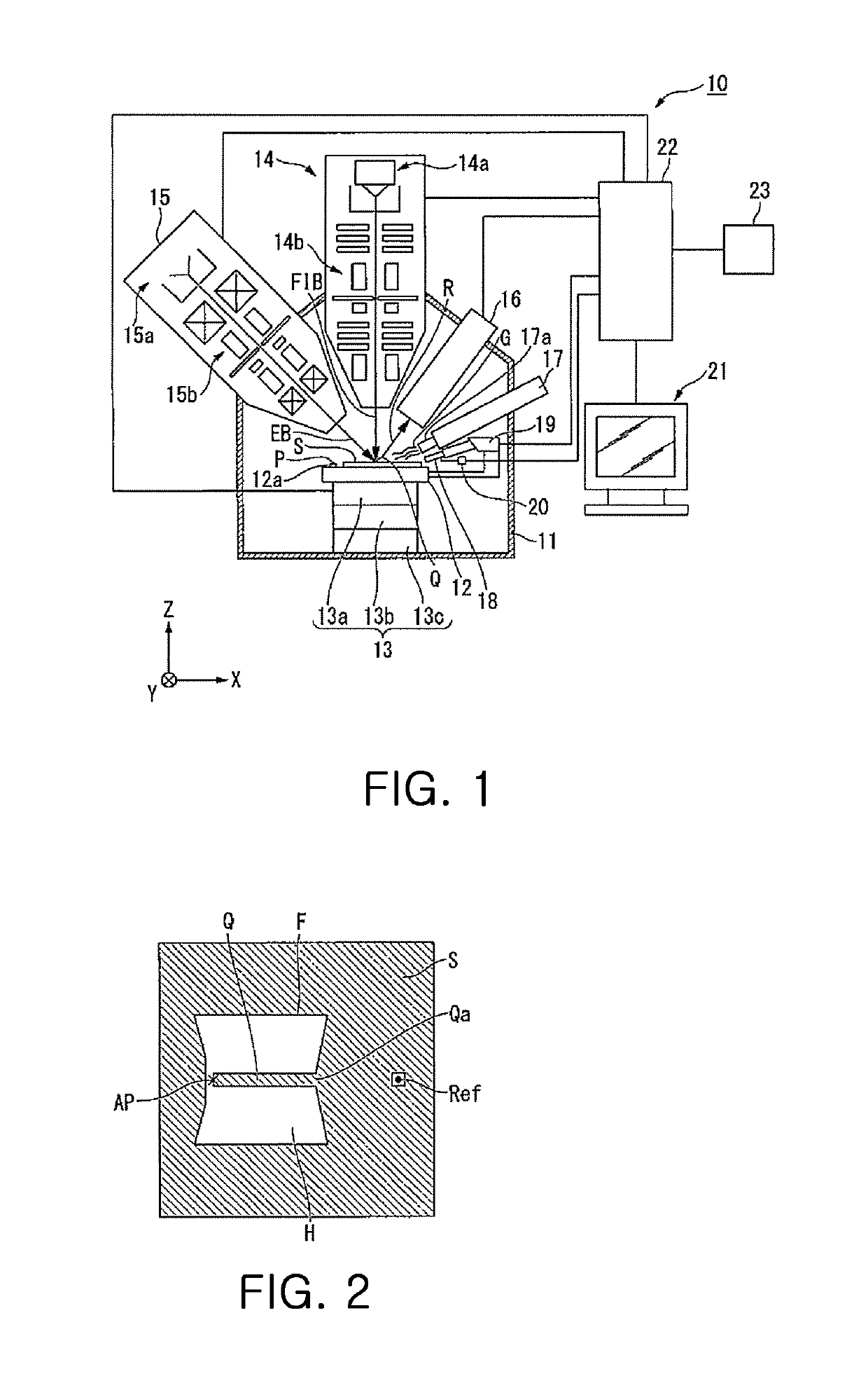
[0062]FIG. 1 is a configuration diagram of a charged particle beam device 10 according to the embodiment of the present invention. As illustrated in FIG. 1, the charged particle beam device 10 according to the embodiment of the present invention includes a sample chamber 11 capable of maintaining an inside thereof under a vacuum state, a stage 12 capable of fixing a sample S and a sample piece holder P inside the sample chamber 11, and a stage driving mechanism 13 configured to drive the stage 12. The charged particle beam device 10 includes a focused ion beam irradiation optical system 14 configured to irradiate an irradiation target within a predetermined irradiation area (that is, scan range) inside the sample chamber 11 with a focused ion beam (FIB). The charged particle beam device 10 includes an electron beam irradiation optical system 15 configured to irradiate the irradiation target within the predetermined irradiation area inside the sample chamber 11 with an electron beam ...


PUM


Abstract

To automatically repeat an operation of isolating a sample piece, which is formed by processing a sample with an ion beam, and transferring the sample piece to a sample piece holder, a charged particle beam device includes a computer configured to perform control so that, without rotating a needle with which the sample piece is fixed to the sample piece holder, a deposition film deposited on the needle is irradiated with a charged particle beam from a charged particle beam irradiation optical system.

Description

CROSS REFERENCE TO RELATED APPLICATION[0001]The present application claims priority to Japanese Patent Application No. JP 2018-069105, filed Mar. 30, 2018, the entire contents of which are incorporated herein for all purposes by this reference.BACKGROUND OF THE INVENTION1. Field of the Invention[0002]The present invention relates to a charged particle beam device configured to automatically perform sampling.2. Description of the Related Art[0003]In preparing a sample piece for observation with a transmission electron microscope, a technology of processing with a focused ion beam is used. There is known an automatic sample piece manufacturing apparatus capable of automatically performing sampling in which a sample piece, which is manufactured by irradiating a sample with the focused ion beam, is isolated and transferred to a sample holder (see Japanese Patent Application Laid-open No. 2016-050853).[0004]There is also known a charged particle beam device configured to shift a posture ...

Claims


Application Information

Patent Timeline
IPC IPC(8): H01J37/305H01J37/20
CPCH01J37/20H01J37/3053H01J2237/20285H01J2237/20214H01J37/3056G01N1/286G01N23/04G01N2001/2873H01J2237/31745H01J37/3023H01J2237/208H01J37/3045H01J37/28H01J2237/31749
Inventor SUZUKI, MASATOTOMIMATSU, SATOSHISATO, MAKOTOASAHATA, TATSUYA
Owner HITACHI HIGH TECH SCI CORP
Learn More