Input Third Order Intercept Point in Low Noise Amplifier with Degeneration Tank Circuit

a low-noise amplifier and degeneration tank technology, applied in the field of rf front ends, can solve the problems of reducing the overall receiver performance, introducing distortion to the amplified input signal, and many rf transceivers are quite complex two-way radios, and achieve low power consumption, high third-order intercept, and low-noise amplifiers.

Active Publication Date: 2019-09-19
PSEMI CORP
View PDF1 Cites 4 Cited by
  • Summary
  • Abstract
  • Description
  • Claims
  • Application Information

AI Technical Summary

Benefits of technology

[0013]A receiver front end is disclosed herein having a low noise amplifier (LNA) with relatively high third order intercept measured at the input (IIP3), low power consumption and low noise figure. In accordance with some embodiments of the disclosed method and apparatus, the LNA is configured as a cascode, similar to that shown in FIG. 1 and discussed above. That is, the LNA has two stacked transistors. The first transistor is configured as a “common source” input transistor, e.g., input field effect transistor (FET). T

Problems solved by technology

Many RF transceivers are quite complex two-way radios that transmit and receive RF signals across multiple frequencies in multiple bands using one or more signaling protocols.
Nonlinearity in the LNA introduces disto

Method used


Image

  • Input Third Order Intercept Point in Low Noise Amplifier with Degeneration Tank Circuit
  • Input Third Order Intercept Point in Low Noise Amplifier with Degeneration Tank Circuit
  • Input Third Order Intercept Point in Low Noise Amplifier with Degeneration Tank Circuit

Examples


Embodiment Construction

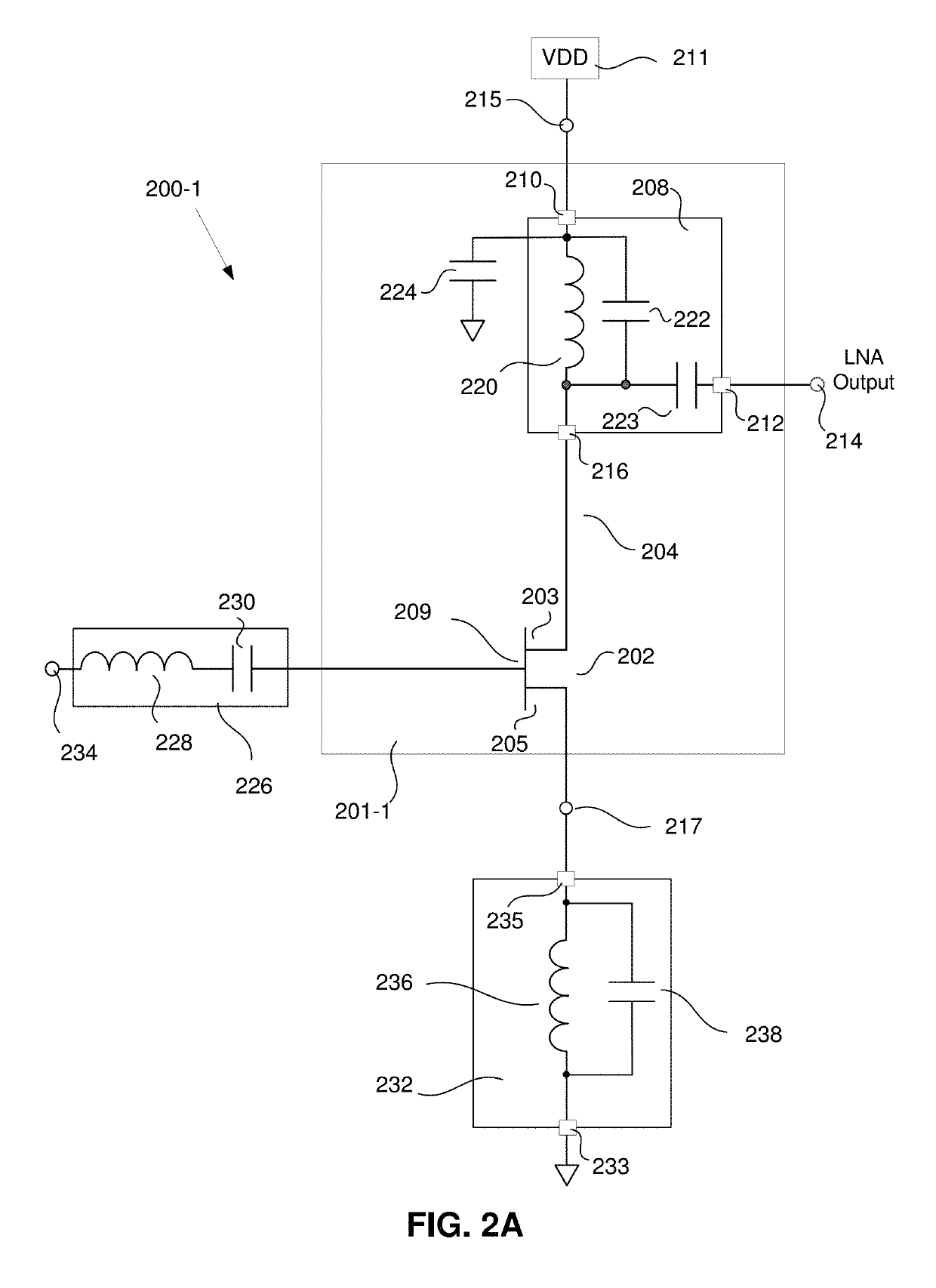
[0033]FIG. 2A is a simplified schematic of a front end amplifier 200-1 of a communication receiver having an enhanced input third order intercept point (IIP3). In some embodiments of the disclosed method and apparatus, the front end amplifier 200 comprises a low noise amplifier (LNA) 201-1. The LNA 201-1 has a signal input 234, a signal output 214, a supply current input 215 and a supply current output 217. The LNA 201-1 comprises a transistor 202. In some such embodiments, the transistor is a field effect transistor (FET) 202. However, it will be understood by those skilled in the art that other types of transistors may be used, including, but not limited to, bipolar junction transistors. Furthermore, any type of FET may be used to implement the LNA 201-1, including, but not limited to metal-oxide semiconductors (MOSFETs), junction field effect transistors (JFETs), insulated gate FETs (IGFETs), metal semiconductor FETs (MESFETs), etc. While some types of transistors may be better s...


PUM


Abstract

A receiver front end having low noise amplifiers (LNAs) with enhanced input third order intercept point is disclosed herein. A cascode having a “common source” configured input FET and a “common gate” configured load FET have a degeneration circuit comprising a tank circuit tuned to a harmonic of the operating frequency.

Description

BACKGROUND(1) Technical Field[0001]Various embodiments described herein relate to RF front ends and more particularly to low noise amplifiers for use in communications equipment.(2) Background[0002]Many modern electronic systems include radio frequency (RF) transceivers; examples include personal computers, tablet computers, wireless network components, televisions, cable system “set top” boxes, radar systems, and cellular telephones. Many RF transceivers are quite complex two-way radios that transmit and receive RF signals across multiple frequencies in multiple bands using one or more signaling protocols. As an example, a modern “smart telephone” may include RF transceiver circuitry capable of operating on different cellular communications systems (e.g., GSM and LTE), on different wireless network frequencies and protocols (e.g., IEEE 802.1bg at 2.4 GHz, and IEEE 802.1n at 2.4 GHz and 5 GHz), and on “personal” area networks (e.g., Bluetooth based systems).[0003]The front end of a ...

Claims


Application Information

Patent Timeline
IPC IPC(8): H03F1/26H03F3/193H03F1/56H04B1/16
CPCH04B1/16H03F2200/294H03F3/193H03F2200/222H03F1/26H03F2200/451H03F1/565H03F1/223H03F1/3205H04B1/0458H04B1/18H04B1/525
Inventor GAYNOR, MICHAEL P.
Owner PSEMI CORP
Why Eureka
Try Eureka