
Improved microlayer membranes, mproved battery separators, and related methods

a technology of battery separator and microlayer membrane, which is applied in the direction of battery separator, separator, separator, etc., can solve the problems of increasing the requirements of battery separators, not fully optimizing the balance of strength and/or performance properties, and the separator formed by laminating monolayers may also eventually not meet the ever-increasing demands. , to achieve the effect of improving dielectric breakdown strength, improving strength, and improving shutdown

Pending Publication Date: 2019-08-29
CELGARD LLC
View PDF2 Cites 1 Cited by
  • Summary
  • Abstract
  • Description
  • Claims
  • Application Information

AI Technical Summary

Benefits of technology

The patent text describes a new type of battery separator that is made up of multiple layers of polymer membranes. These membranes have improved properties, such as better strength and durability, which make them safer and more reliable than previous battery separators. The membranes can be used in lithium batteries, resulting in batteries with improved safety and durability. The method for making these membranes involves co-extruding multiple polymer mixtures to form a bi-layer, tri-layer, or multi-layer film, which is then laminated together to create the final membrane.

Problems solved by technology

The aforementioned methods may not fully optimize a balance of strength and / or performance properties for use in applications such as certain primary and / or secondary batteries, such as lithium ion rechargeable batteries.
This is especially true as the battery separator requirements are becoming more demanding as customers want thinner and stronger battery separators.
Separators formed by laminating monolayers also may eventually not satisfy the ever-increasing demands.

Method used


Image

  • Improved microlayer membranes, mproved battery separators, and related methods
  • Improved microlayer membranes, mproved battery separators, and related methods
  • Improved microlayer membranes, mproved battery separators, and related methods

Examples


example 1 (ex 1)

Example 1(EX 1)

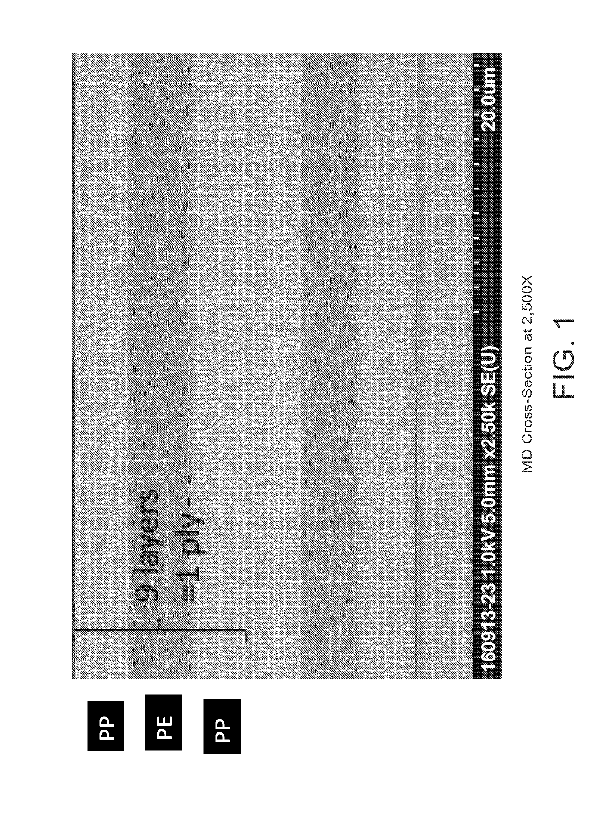
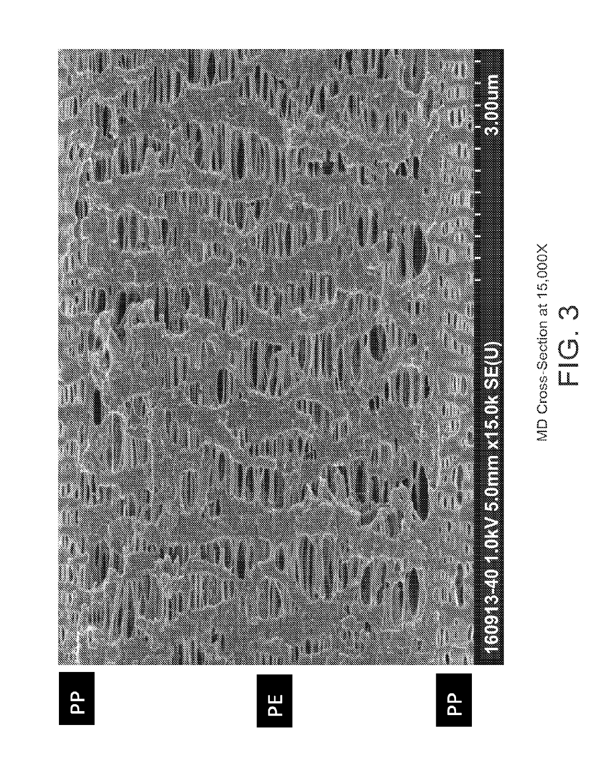
[0175](PP / PP / PP)(PE / PE / PE)(PP / PP / PP)—all PP layers are made of a homopolymer PP, density=0.90 g / cm3, MFR in the range of 0.5 MFR-2 MFR. All PE layers are made of a blend of 95% high density polyethylene with melt index between 0.25-0.5 g / 10 min at 2.16 kg and 190 deg C., and density range between 0.955-0.966 g / cm3 and 5% mLLDPE.

example 2 (ex 2)

Example 2(EX 2)

[0176](PP1 / PP2 / PP1)(PE1 / PE2 / PE3)(PP1 / PP2 / PP1)—PP1 is a homopolymer PP. PP2 a homopolymer polypropylene having a higher MFR than PP1. PE1 high density polyethylene with melt index between 0.25-0.5 g / 10 min at 2.16 kg and 190 deg C. PE2 is an ultrahigh density polyethylene. PE3 is a blend of 95% high density polyethylene with melt index between 0.25-0.5 g / 10 min at 2.16 kg and 190 deg C., and density range between 0.955-0.966 g / cm3 and 5% mLLDPE.

example 3 (ex 3)

Example 3(EX 3)

[0177](PP / PP / PP)(PE1 / PE2 / PE1)(PP / PP / PP)—PP layers are made of a homopolymer PP, density=0.90 g / cm3, MFR in the range of 0.5 MFR-2 MFR. PE1 is made of high density polyethylene with melt index between 0.25-0.5 g / 10 min at 2.16 kg and 190 deg C. PE2 is made of an ultrahigh molecular weight polyethylene.


PUM

PropertyMeasurementUnit
Fractionaaaaaaaaaa
Fractionaaaaaaaaaa
Fractionaaaaaaaaaa

Abstract

Described herein is a multilayer microporous film or membrane that may exhibit improved properties, including improved dielectric break down and strength, compared to prior monolayer or tri-layer microporous membranes of the same thickness. The preferred multilayer microporous membrane comprises microlayers and one or more lamination barriers. Also disclosed is a battery separator or battery comprising one or more of the multilayer microporous films or membranes. The inventive battery and battery separator is preferably safer and more robust than batteries and battery separators using prior monolayer and tri-layer microporous membranes. Also, described herein is a method for making the multilayer microporous separators, membranes or films described herein.

Description

PRIORITY CLAIM[0001]This application claims the benefit of and priority under 35 U.S.C. § 119(e)(1) to both U.S. Provisional Application No. 62 / 508,360 filed on May 18, 2017 and U.S. Provisional Application No. 62 / 420,781 filed on Nov. 11, 2016. These provisional applications are each incorporated by reference herein in their entirety.FIELD OF THE INVENTION[0002]In accordance with at least selected embodiments, the application, disclosure or invention relates to novel or improved membranes, separator membranes, separators, battery separators, secondary lithium battery separators, multilayer membranes, multilayer separator membranes, multilayer separators, multilayer battery separators, multilayer secondary lithium battery separators, and / or multilayer battery separators with improved properties, novel or improved batteries, capacitors, fuel cells, lithium batteries, lithium ion batteries, secondary lithium batteries, and / or secondary lithium ion batteries, and / or methods for making ...

Claims


Application Information

Patent Timeline
IPC IPC(8): H01M2/16H01M2/14B29C48/00B29C48/08B29C48/21B32B27/08B32B27/32H01M50/406H01M50/417H01M50/457H01M50/489H01M50/491H01M50/494
CPCH01M2/1686H01M2/1653H01M2/145H01M2/1666B29C48/0018B29C48/0021B32B2457/10B29C48/21B32B27/08H01M10/0525B29L2031/3468B29K2023/06B29C48/08B32B27/32B32B27/00H01M10/052B29C48/07B32B3/26B32B5/022B32B7/02B32B5/024B32B5/028B32B7/04B32B27/12B32B5/26B32B25/08B32B2250/242B32B2250/02B32B2250/04B32B2250/03B32B2250/05B32B27/20B32B27/304B32B27/306B32B27/22B32B27/28B32B27/34B32B27/36B32B27/286B32B27/322B32B27/285B32B27/308B32B27/18B32B27/302B32B2255/20B32B2255/10B32B2255/02B32B2255/28B32B2255/26B32B2264/0257B32B2264/107B32B2270/00B32B2307/51B32B2307/54B32B2307/306B32B2307/736B32B2307/72B32B2307/518B32B2307/704B32B2307/204B32B2307/50B32B2307/732B32B2307/746H01M50/417H01M50/489H01M50/406H01M50/457H01M50/491H01M50/494Y02E60/10B29L2031/755H01M50/449H01M50/434B29K2023/12B32B2305/026B32B2305/30B32B2323/10B32B2323/04H01M50/497B32B2307/70B32B2307/726
Inventor XIAO, KANG KARENPENEGAR, ERIC J.KONDO, TAKAHIKONARK, ROBERTWHITE, ERIC R.ZHANG, XIAOMINSTOKES, KRISTOFFER K.REINARTZ, STEFANOKADA
Owner CELGARD LLC
Learn More