Light irradiation device and light irradiation system
a technology of light irradiation and light irradiation, which is applied in the direction of automatic actuation, television system, instruments, etc., can solve the problems of large accident, blade breakage, and problem of birds striking
- Summary
- Abstract
- Description
- Claims
- Application Information
AI Technical Summary
Benefits of technology
Problems solved by technology
Method used
Image
Examples
first example embodiment
[0064][Configuration]
[0065]First, a light irradiation device 1 according to a first example embodiment of the present invention will be described with reference to corresponding drawings.
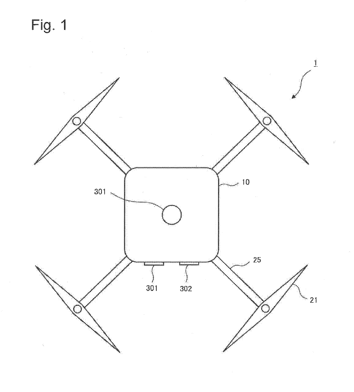
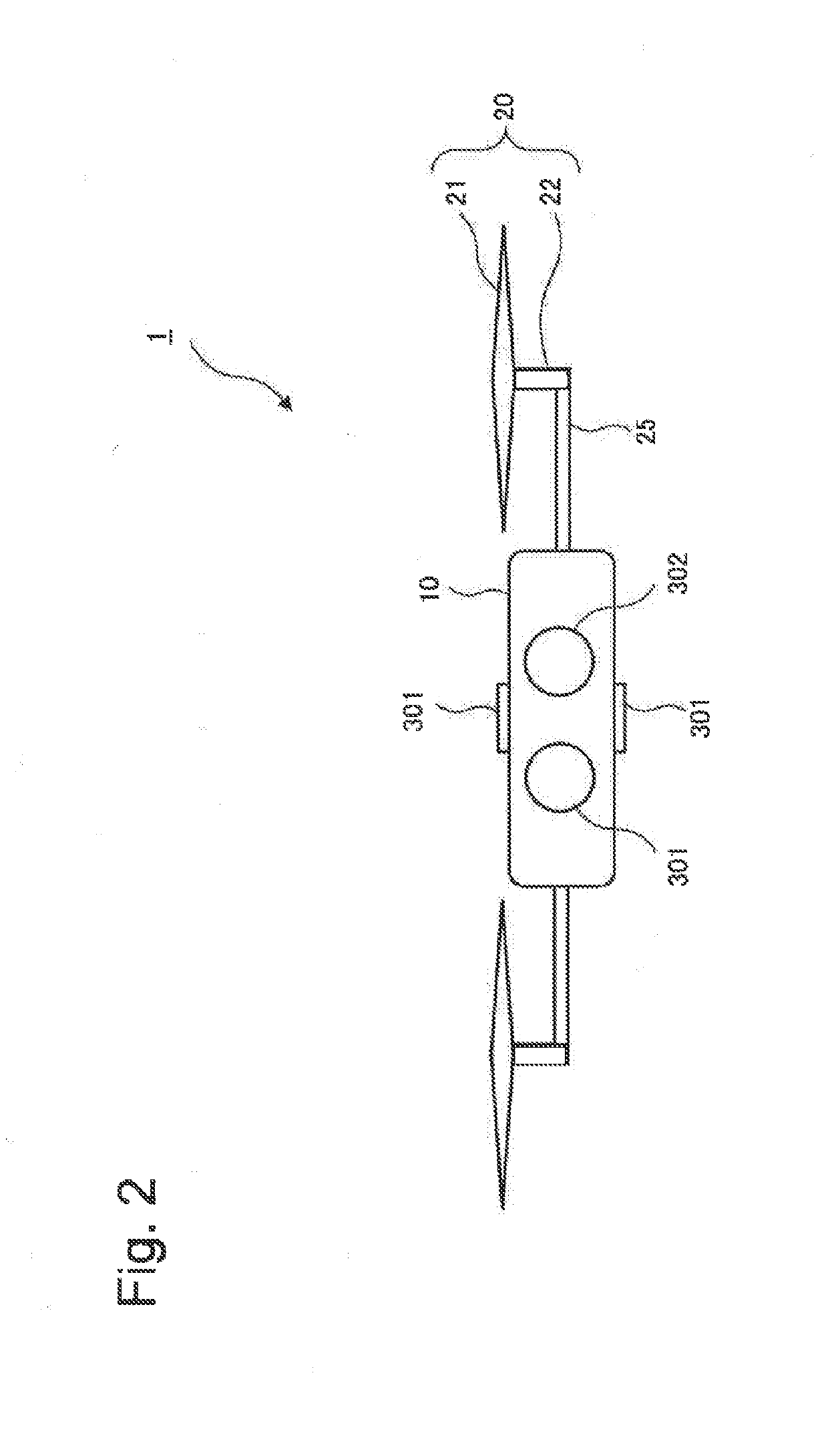
[0066]FIG. 1 is a bottom view of the light irradiation device 1 according to the present example embodiment. FIG. 2 is a side view of the light irradiation device 1 according to the present example embodiment. A top view, a rear view, an oblique view, and the like of the light irradiation device 1 are omitted.
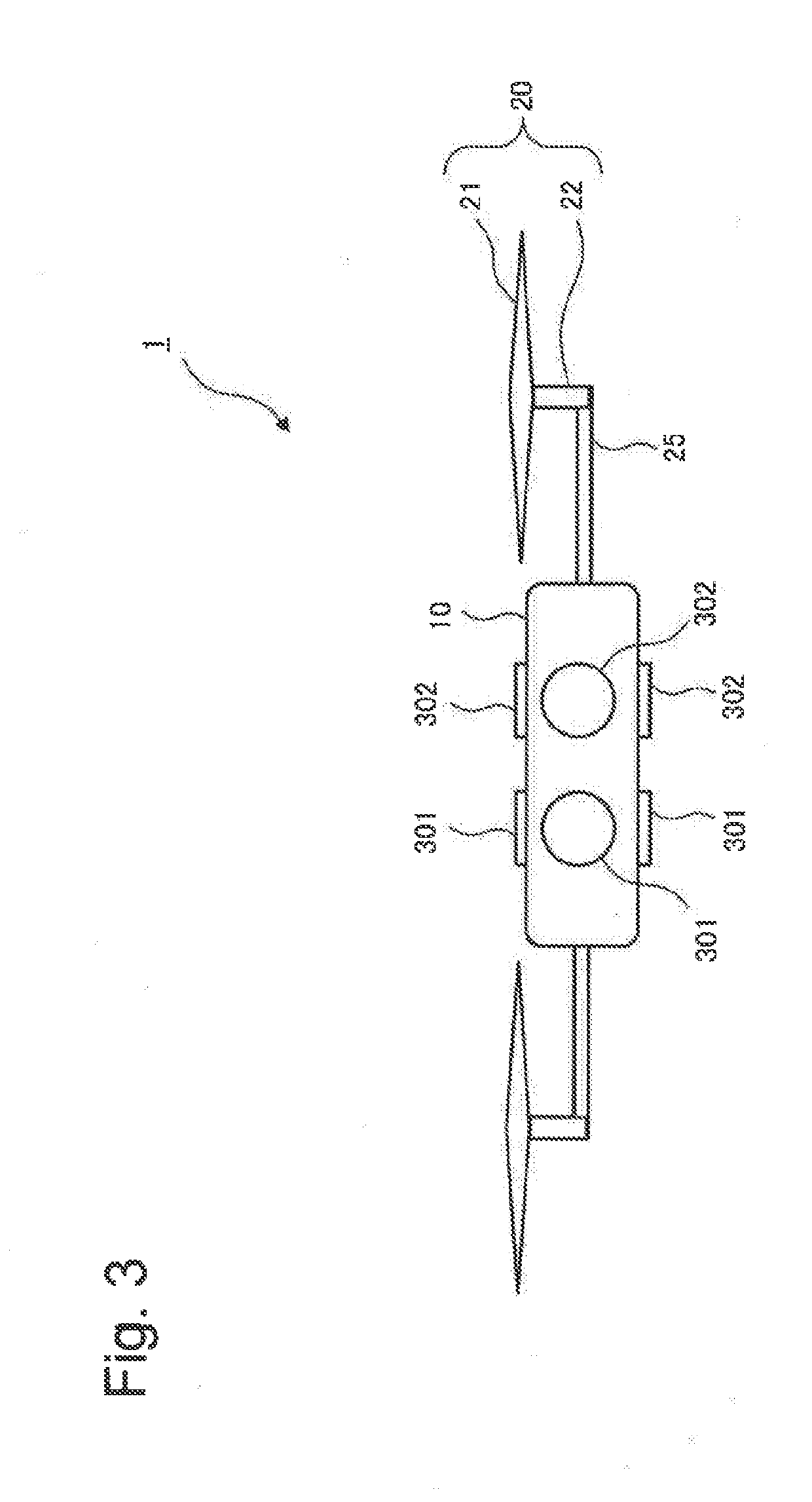
[0067]The light irradiation device 1 according to the present example embodiment includes a main body 10 mounted with a camera function for imaging a monitoring region and a projector function for irradiating a target (hereinafter, referred to as a light irradiation target) moving in the monitoring region with light. As in FIG. 1 and FIG. 2, a camera 301 and a projector 302 are exposed to the outside from the main body 10 of the light irradiation device 1. In FIG. 1 and FIG. 2, only tip portion...
second example embodiment
[0168]Next, a light irradiation device 2 according to a second example embodiment of the present invention will be described with reference to corresponding drawings. FIG. 19 is a front view of the light irradiation device 2 according to the present example embodiment. The light irradiation device 2 includes a sound wave emission port 305 that generates a sound wave. The light irradiation device 2 can irradiate a light irradiation target with a sound wave, together with signal light. The sound wave emission port 305 is an opening for irradiating a light irradiation target with a sound wave, and a shape thereof is not limited.
[0169]As in FIG. 20, the light irradiation device 2 according to the present example embodiment includes a configuration in which a sound wave output means 351 is added to the configuration of the light irradiation device 1 according to the first example embodiment. Further, as in FIG. 21, a control means 33-2 of the light irradiation device 2 according to the p...
third example embodiment
[0175]Next, a light irradiation device 3 according to a second example embodiment of the present invention will be described with reference to corresponding drawings. FIG. 22 is a front view of the light irradiation device 3 according to the present example embodiment. The light irradiation device 3 includes a sound wave input port 306 to which a sound wave is input. The light irradiation device 3 receives a sound wave during monitoring of a monitoring region. The sound wave input port 306 is an opening to which a sound wave is input, and a shape thereof is not limited.
[0176]As in FIG. 23, the light irradiation device 3 according to the present example embodiment includes a configuration in which a sound wave input means 352 is added to the configuration of the light irradiation device 1 according to the first example embodiment. Further, as in FIG. 24, a control means 33-3 of the light irradiation device 3 according to the present example embodiment includes a configuration in whic...
PUM
 Abstract
Description
Claims
Application Information
 - R&D
- Intellectual Property
- Life Sciences
- Materials
- Tech Scout
- Unparalleled Data Quality
- Higher Quality Content
- 60% Fewer Hallucinations
Browse by: Latest US Patents, China's latest patents, Technical Efficacy Thesaurus, Application Domain, Technology Topic, Popular Technical Reports.
© 2025 PatSnap. All rights reserved.Legal|Privacy policy|Modern Slavery Act Transparency Statement|Sitemap|About US| Contact US: help@patsnap.com


