Object detection and detection confidence suitable for autonomous driving

a technology for autonomous driving and object detection, applied in scene recognition, instruments, reradiation, etc., can solve problems such as false detections or positives, improper paths and even collisions, and conventional approaches that may not have the desired accuracy, so as to improve the accuracy of final detected objects, accurate indicate probability, and distinguish between adjacent objects

Active Publication Date: 2019-08-22
NVIDIA CORP
View PDF0 Cites 218 Cited by
  • Summary
  • Abstract
  • Description
  • Claims
  • Application Information

AI Technical Summary

Benefits of technology

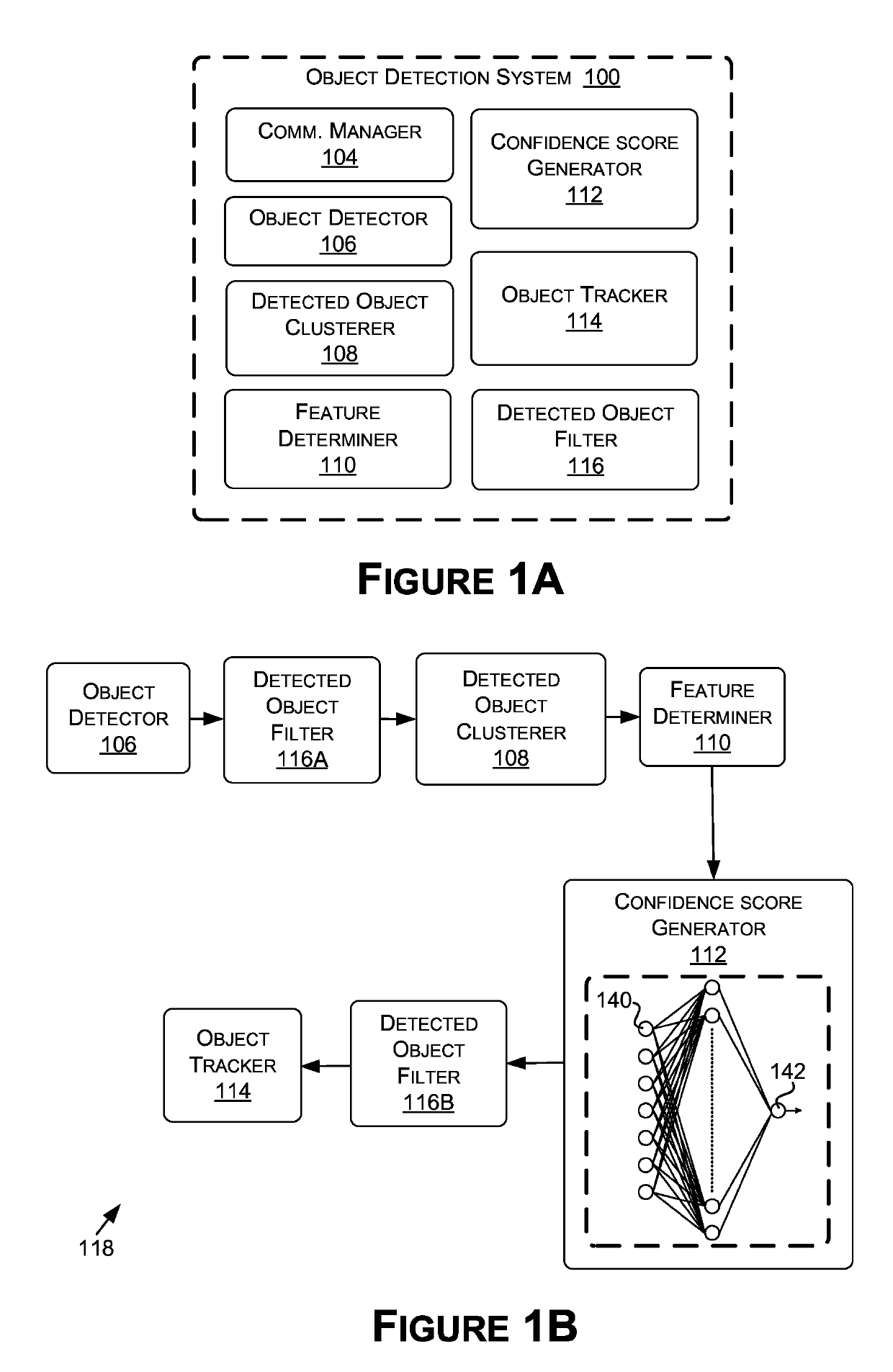
[0006]Embodiments of the present disclosure relate to object detection and detection confidence suitable for autonomous driving. In contrast to conventional approaches that determine a confidence value for an aggregated detection that may not be directly interpreted as a confidence or probability measure or may only correspond to a small portion of an image, disclosed approaches allow for the determination of a confidence score (e.g., a scalar value) that may be directly interpreted as a confidence measure and may accurately indicate a probability that an aggregated detection corresponds to an actual object represented in image data. Thus, false or missed detections may be less likely to occur when employing the confidence score.
[0007]In some examples, a Machine Learning Model (MLM), such as a multi-layer perceptron network, may be trained to determine the confidence score using features generated from detected objects (e.g., in a field(s) of view of a vehicle). The MLM may learn to account for the complex relationships between detected objects for different spatial element regions in generating the confidence score. Further, the confidence score may be a bounded value that provides direct interpretability while accounting for any number of raw detected objects that are part of an aggregated detection. Thus, use of the confidence score is less likely to lead to false detections compared to conventional approaches, such as those described above.
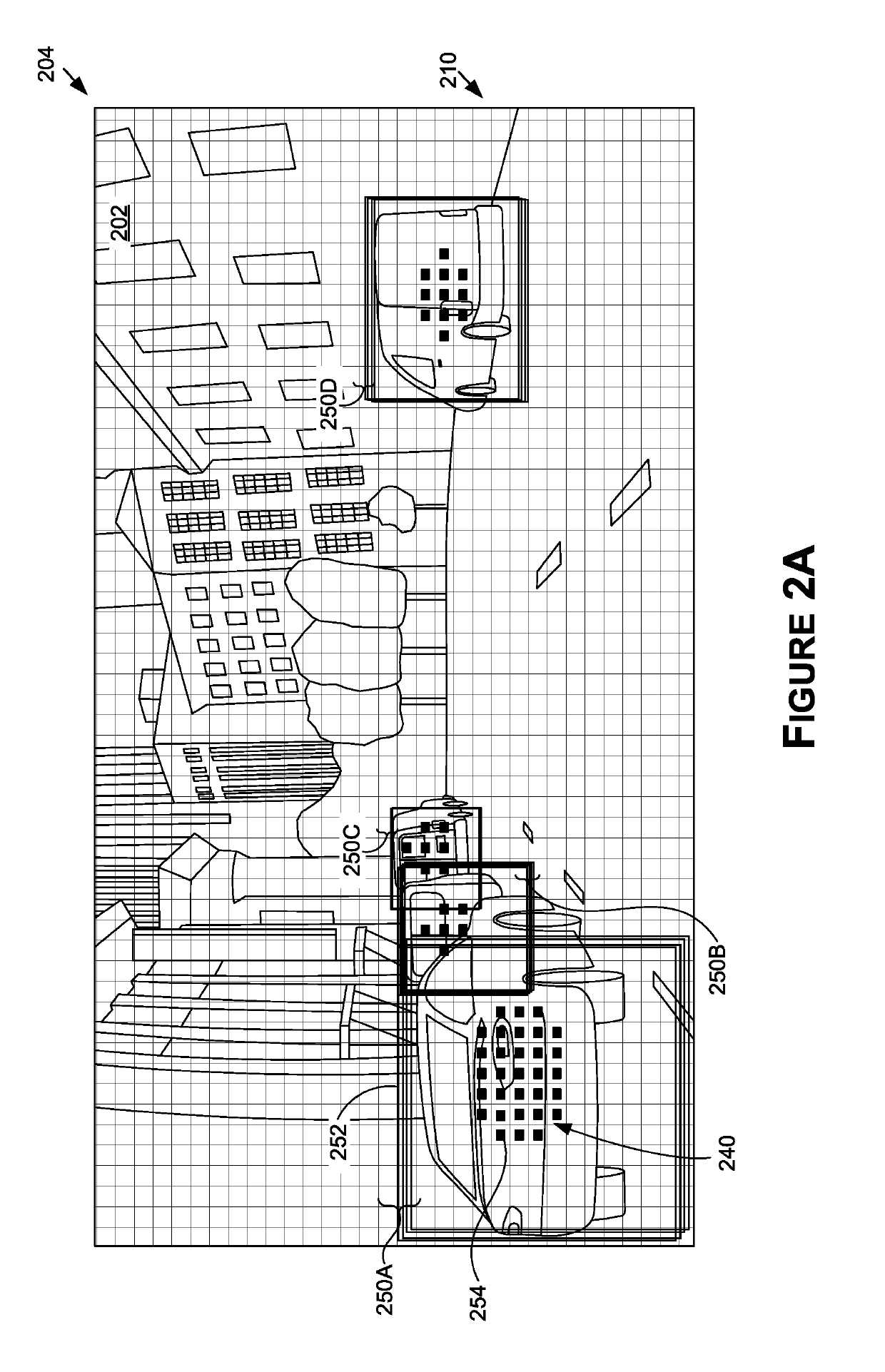
[0008]In further contrast to conventional approaches for training a CNN for object detection that only assign a single spatial element region to a set of bounding box coordinates, disclosed approaches may improve the accuracy of final detected objects by allowing a set of bounding box coordinates to be assigned to multiple spatial element regions (e.g., using an elliptical ground truth that corresponds to multiple spatial element regions) for training, and / or for soft coverage values (e.g., in a range from 1 to 0) to be assigned to spatial element regions in ground truth data used to train the CNN.
[0009]In some examples, a size of a shape that is at least partially within an object region (e.g., ground truth bounding box region) is computed using a dimension of the object region. The shape may then be used to determine coverage values for spatial element regions of the training image used to train the CNN (e.g., by drawing at least some of the shape in a ground truth tensor). Provided approaches may further allow for determining a coverage value for a spatial element region when the spatial element region corresponds to multiple object regions (indicating different objects). In further respects, a dead-zone area may be used to spatially separate coverage values that correspond to different object regions (indicating different objects). This may train the CNN to better distinguish between adjacent objects. For example, the CNN trained in this manner may provide lower coverage values for areas between adjacent objects.

Problems solved by technology

However, conventional approaches may not have a desired accuracy and as a result, may miss, or generate false or delayed object detections that may lead to improper paths and even collisions.
In practice, this approach may lead to false detections or positives, as the maximum coverage value may only correspond to a small portion of the image.
However, because the sum is unbounded, the sum may not be directly interpreted as a confidence or probability measure, which may also lead to false or missed detections (e.g., a variable number of detections may be part of a cluster so the sum does not provide a relative measure cross-cluster).
However, in many cases, it may be difficult to assign an object to only one spatial element region, or definitively determine whether an object is depicted in that spatial element region.
As a result of this training approach, the CNN, as described above, may generate false detections from an object detector or false positives for aggregated detections, thereby decreasing the efficacy of the CNN.

Method used


Image

  • Object detection and detection confidence suitable for autonomous driving
  • Object detection and detection confidence suitable for autonomous driving
  • Object detection and detection confidence suitable for autonomous driving

Examples


example autonomous

[0209 Vehicle

[0210]FIG. 15A is an illustration of an example autonomous vehicle 1500, in accordance with some embodiments of the present disclosure. The autonomous vehicle 1500 (alternatively referred to herein as the “vehicle 1500”) may include a passenger vehicle, such as a car, a truck, a bus, and / or another type of vehicle that accommodates one or more passengers. Autonomous vehicles are generally described in terms of automation levels, defined by the National Highway Traffic Safety Administration (NHTSA), a division of the US Department of Transportation, and the Society of Automotive Engineers (SAE) “Taxonomy and Definitions for Terms Related to Driving Automation Systems for On-Road Motor Vehicles” (Standard No. J3016-201806, published on Jun. 15, 2018, Standard No. J3016-201609, published on Sep. 30, 2016, and previous and future versions of this standard). The vehicle 1500 may be capable of functionality in accordance with one or more of Level 3-Level 5 of the autonomous d...


PUM


Abstract

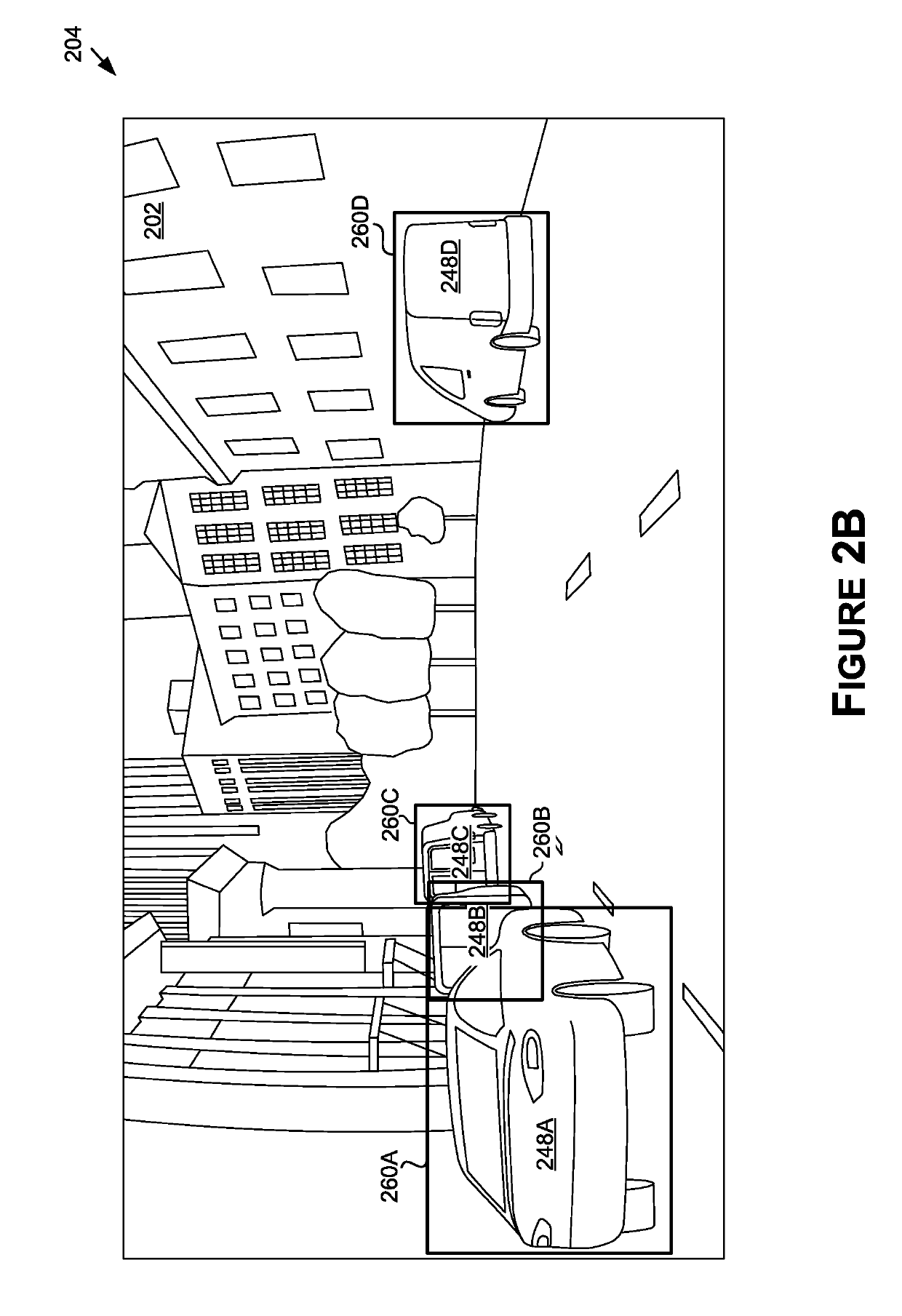
In various examples, detected object data representative of locations of detected objects in a field of view may be determined. One or more clusters of the detected objects may be generated based at least in part on the locations and features of the cluster may be determined for use as inputs to a machine learning model(s). A confidence score, computed by the machine learning model(s) based at least in part on the inputs, may be received, where the confidence score may be representative of a probability that the cluster corresponds to an object depicted at least partially in the field of view. Further examples provide approaches for determining ground truth data for training object detectors, such as for determining coverage values for ground truth objects using associated shapes, and for determining soft coverage values for ground truth objects.

Description

CROSS-REFERENCE TO RELATED APPLICATIONS[0001]This application claims the benefit of U.S. Provisional Application No. 62 / 631,781, filed on Feb. 18, 2018, which is hereby incorporated by reference in its entirety.BACKGROUND[0002]To operate safely, autonomous vehicles should account for objects—such as vehicles, people, trees, animals, buildings, signs, and poles—when planning paths through the environment. To do so, an object detector may be used to accurately detect objects depicted in an image(s) in real-time (e.g., images captured using one or more sensors mounted on the autonomous vehicle). However, conventional approaches may not have a desired accuracy and as a result, may miss, or generate false or delayed object detections that may lead to improper paths and even collisions.[0003]A conventional system for object detection may use a convolutional neural network (CNN) that provides coverage values and bounding boxes for a grid of spatial element regions of the image. Each covera...

Claims


Application Information

Patent Timeline
Patent Type & Authority Applications(United States)
IPC IPC(8): G06K9/00G06K9/46G06K9/62G06V10/46G06V10/762G06V10/764G06V10/774
CPCG06K9/00825G06K9/00805G06K9/46G06K9/6262G01S7/412G01S7/417G01S7/4802G01S13/867G05D1/0246G06N3/084G05D1/00G01S2013/9318G01S2013/9323G01S17/931G06V20/58G06V10/255G06V10/454G06V10/46G06V10/762G06V10/764G06V10/774G06N3/047G06N3/048G06N3/044G06N3/045G06F18/23B60W50/00G06F16/35G06V20/584G06N20/00G06V10/7715G06F18/214G06F18/217G06F18/2414
Inventor KOIVISTO, TOMMIJANIS, PEKKAKUOSMANEN, TEROROMAN, TIMOSARATHY, SRIYAZHANG, WILLIAMASSAF, NIZARTRACEY, COLIN
Owner NVIDIA CORP
Why Eureka
Try Eureka