Eureka AIR delivers breakthrough ideas for toughest innovation challenges, trusted by R&D personnel around the world.

Method for authorization pairing

Active Publication Date: 2019-08-08
TEKTRO TECH
View PDF0 Cites 5 Cited by
  • Summary
  • Abstract
  • Description
  • Claims
  • Application Information

AI Technical Summary

Benefits of technology

The present patent proposes an easy and secure method for pairing electronic derailleur system components through an authorization device. This method reduces the number of times the pairing has to be processed again and satisfies the anti-theft demand of the system. The method simplifies the pairing process for users and improves the convenience while preserving the security and anti-theft function of the system.

Problems solved by technology

However, the process of pairing with third-party pairing devices today is too complex.
In practice, often after the electronic derailleur system restarts the power supply, or when replacing one of the components of the electronic derailleur system, the user needs to re-execute the aforementioned pairing process, causing inconvenience.

Method used


Image

  • Method for authorization pairing
  • Method for authorization pairing
  • Method for authorization pairing

Examples


first embodiment

[0031]According to the authorization pairing method disclosed in the second type of the present disclosure, please refer to FIG. 2 and FIG. 4 together, which means that the user replaces the first communication device D1 with the sixth communication device D6 (for example, the first communication device D1 must be replaced because the first communication device D1 is broken). The hardware structure of the sixth communication device D6 and the first communication device D1 are basically the same. When the first communication device D1 is removed from the communication range or the first communication device D1 is powered off, the pairing lines L12, L13 and L14 are all interrupted. The sixth communication device D6 for replacing the first communication device D1 detects that the current connection status is “no pairing connection” after the power is turned on, and does not receive the identification code of the preset pairing communication device to automatically establish the pairing...

second embodiment

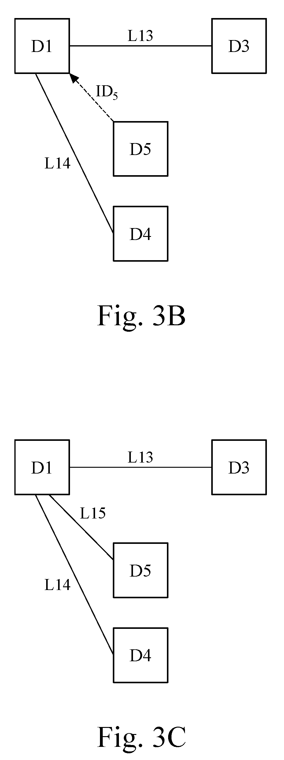
[0035]A second type of the second embodiment will be described below, which puts the “reconfirmation procedure” before the fifth communication device D5 sends the identification code ID5 representing itself In detail, after the power of the fifth communication device D5 is turned on, if the newly added fifth communication device D5 cannot directly establish a pairing with the first communication device D1, then it would perform a second scanning process and simultaneously generates a verification information. The verification information is, for example, “LED light R emitting red light and LED light Y not emitting yellow light”. Before the user triggers the authorization device A to send the authorization signal SA, the user must generate an input message on the input interface of the authorized device A, for example, pressing the red button. The authorization device A converts the input message generated by pressing the red button into a verification signal SR, and the verification...


PUM


Abstract

An authorization pairing method is applicable to an electronic derailleur system for a bicycle, comprising: an authorization device broadcasting a authorization signal, and the first communication device and the second communication device respectively performing the first scanning process and the second scanning process, and each scanning process determine whether the authorization signal is obtained, the first communication device determines whether an identification code is obtained after obtaining the authorization signal, and the second communication device sends an identification code representing the identity after obtaining the authorization signal, and the first communication device obtains the identification code and establishes an authorization pairing with the second communication device.

Description

CROSS-REFERENCE TO RELATED APPLICATIONS[0001]This non-provisional application claims priority under 35 U.S.C. § 119(a) on Patent Application No(s). 107103757 filed in Taiwan, R.O.C. on Feb. 2, 2018, the entire contents of which are hereby incorporated by reference.BACKGROUNDTechnical Field[0002]The present disclosure is related to a pairing method for a communication device, and more particularly to a pairing method for a communication device of a bicycle electronic derailleur system.Related Art[0003]Due to the advancement of wireless communication technology, in the electronic derailleur system of bicycles, it is a popular trend to connect the left and right shifting handles and the front and rear shifters by means of wireless communication. Before the rider rides, the components of the aforementioned electronic derailleur system must be paired. For example, a common form of pairing is that the left shifting handle is paired with the front derailleur and the right shifting handle i...

Claims


Application Information

Patent Timeline
IPC IPC(8): H04W76/11H04W76/14B62M9/122B62M9/132B62M25/08
CPCH04W76/11H04W76/14B62M9/122B62M9/132B62M25/08H04L67/12H04W76/10H04W84/18
Inventor CHUANG, HSUN-YULIN, PAO-WEN
Owner TEKTRO TECH
Why Eureka
Eureka Blog
Learn More