
Method and system for facilitating high-capacity shared memory using dimm from retired servers

a technology of dimm and shared memory, which is applied in the field of data storage, can solve the problems of limiting the bottleneck of the overall performance of the system, and the inability to read caches, so as to facilitate shared memory and expand memory capacity

Active Publication Date: 2019-08-08
ALIBABA GRP HLDG LTD
View PDF7 Cites 2 Cited by
  • Summary
  • Abstract
  • Description
  • Claims
  • Application Information

AI Technical Summary

Benefits of technology

This patent describes a way to expand the memory capacity of a computer system by using a shared memory. The system includes a memory expansion device with additional memory modules that are attached to the computer system through a distinct interface. The system receives input / output requests through this interface and processes them. The selected memory module then executes the request, allowing the computer system to increase its memory capacity. This helps to overcome limitations in the memory bus and ensures efficient memory expansion.

Problems solved by technology

This may result in a conflict between the read cache and other memory allocation requests related to the system memory space.
Because current applications are increasingly memory-hungry, the utilization of the system memory may create a bottleneck in the overall performance of the system.
In addition, the amount of memory in the server (e.g., DRAM) can limit the overall performance of the system.
For example, a single central processing unit (CPU) socket can only support a limited number of dual in-line memory module (DIMM) slots, and a single DIMM has a limited capacity.
Even if DIMMs are added to the server to increase the storage capacity, the high cost of DIMMs can affect the total cost of ownership (TCO).
Thus, the limited capacity of memory in a server, along with the server upgrades which result in retired and unused DIMMs, may create a bottleneck in the performance of the server, and may also create challenges for a reduced TCO in light of the increasing scale of data centers.

Method used


Image

  • Method and system for facilitating high-capacity shared memory using dimm from retired servers
  • Method and system for facilitating high-capacity shared memory using dimm from retired servers
  • Method and system for facilitating high-capacity shared memory using dimm from retired servers

Examples


Embodiment Construction

[0027]The following description is presented to enable any person skilled in the art to make and use the embodiments, and is provided in the context of a particular application and its requirements. Various modifications to the disclosed embodiments will be readily apparent to those skilled in the art, and the general principles defined herein may be applied to other embodiments and applications without departing from the spirit and scope of the present disclosure. Thus, the embodiments described herein are not limited to the embodiments shown, but are to be accorded the widest scope consistent with the principles and features disclosed herein.

Overview

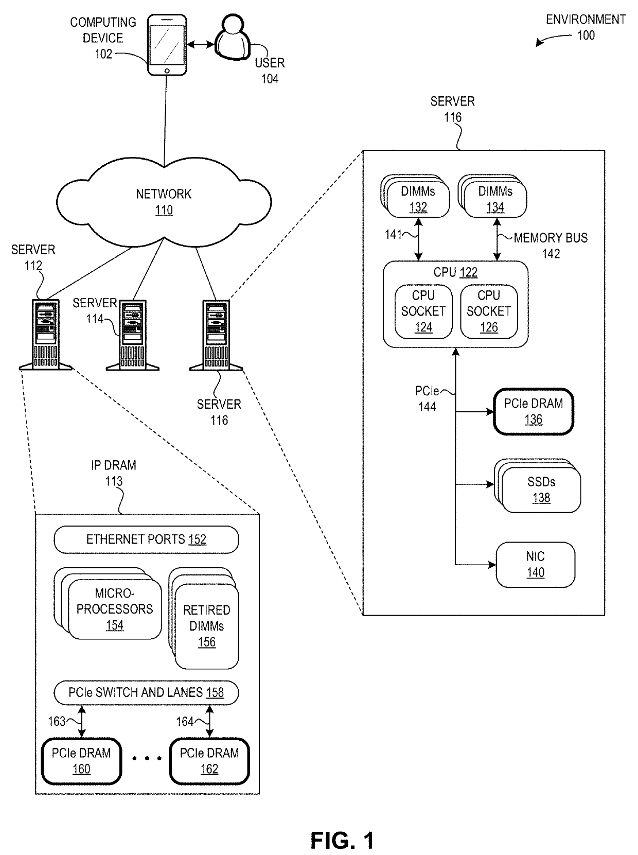
[0028]The embodiments described herein provide a system which solves the problem of the performance bottleneck resulting from limited memory in a server (e.g., DRAM) by creating a shared memory layer in a pluggable or attachable memory expansion device which uses DIMMs from retired servers. As today's applications require an increasing...


PUM


Abstract

One embodiment facilitates a shared memory. During operation, the system receives, by a memory expansion device, an I / O request via a first interface which is distinct from a memory bus, wherein the memory expansion device includes a first set of memory modules, and wherein the memory expansion device is attached to a computer system via the first interface. The system processes, by a controller of the memory expansion device, the I / O request. The system transmits, by the controller via a second interface, the I / O request to a selected memory module. The system executes, by the selected memory module, the I / O request, thereby allowing the computer system to expand memory capacity beyond memory slots available on the memory bus.

Description

BACKGROUNDField[0001]This disclosure is generally related to the field of data storage. More specifically, this disclosure is related to a method and system for facilitating a high-capacity shared memory layer using volatile memory modules (e.g., dual in-line memory modules or DIMMs) from a retired server.Related Art[0002]The proliferation of the Internet and e-commerce continues to create a vast amount of digital content. Various storage systems and servers have been created to access and store such digital content. A storage system or server can include volatile memory (e.g., dynamic random access memory (DRAM)) and multiple drives (e.g., a solid state drive (SSD)), where a drive can include non-volatile memory for persistent storage (e.g., NAND flash). The memory in a server plays a crucial role in the performance and capacity of a storage system. For example, as current applications require an increasing amount of memory, the read latency becomes an important feature. In current...

Claims


Application Information

Patent Timeline
Patent Type & Authority Applications(United States)
IPC IPC(8): G06F3/06
CPCG06F3/0659G06F3/0611G06F3/0673G06F3/061G06F3/0656G06F3/0688G06F13/102G06F13/1673G06F3/0664G06F13/385
Inventor LI, SHU
Owner ALIBABA GRP HLDG LTD
Learn More