
System and method for noninvasively assessing bioengineered organs

a bioengineered organ and non-invasive technology, applied in the field of systems and methods for non-invasively evaluating engineered tissues and organs, can solve the problems of preventing the use of many optical imaging techniques, human livers can easily exceed the thickness of 5 cm, and organoids developing in bioreactors typically lack mechanisms to repair dna damage caused

Pending Publication Date: 2019-08-08
THE UNIV OF NORTH CAROLINA AT CHAPEL HILL +1
View PDF2 Cites 5 Cited by
  • Summary
  • Abstract
  • Description
  • Claims
  • Application Information

AI Technical Summary

Benefits of technology

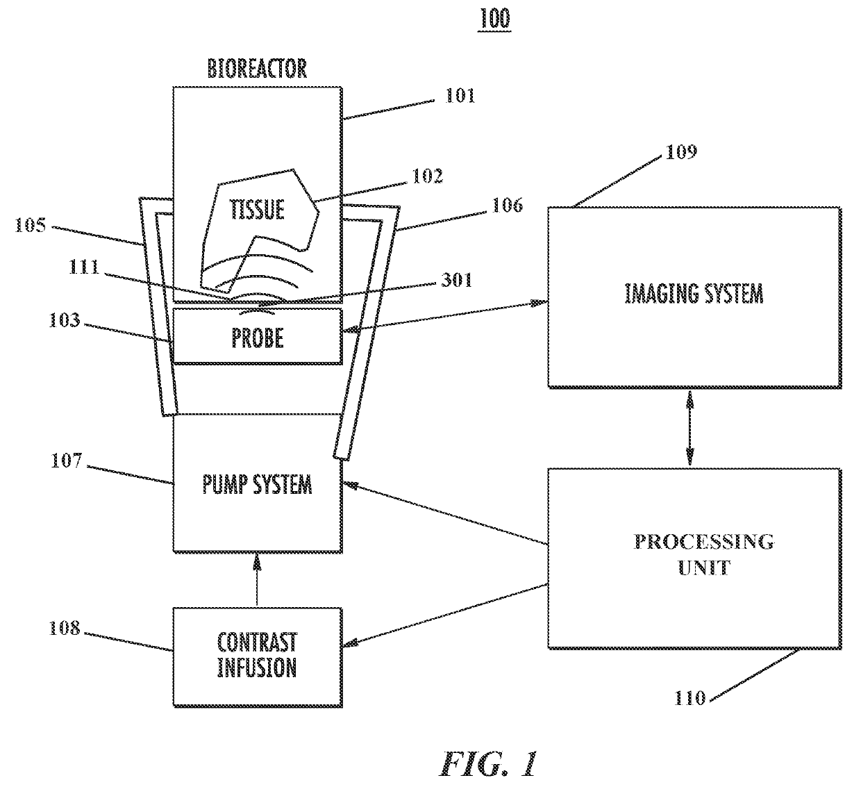
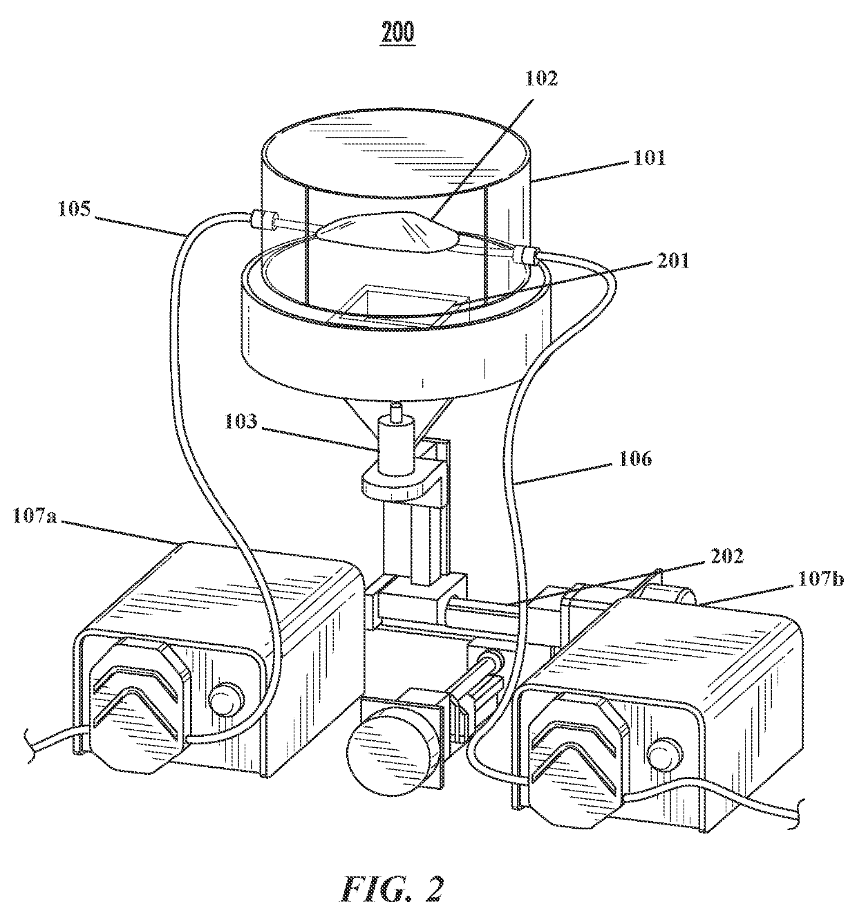
The patent text describes systems for analyzing cell distribution in engineered tissue samples. These systems include an imaging system that uses ultrasound to analyze the tissue samples. The systems can be used in a bioreactor where the tissue samples are present. The ultrasound transducer can be located outside or inside the bioreactor. The tissue samples can be decellularized or recellularized. The systems can also include a pump for regulating the flow of fluid in the bioreactor. Overall, the systems provide a way to analyze and characterize engineered tissue samples using ultrasound imaging.

Problems solved by technology

Ionizing radiation can be tolerated by living organisms, but organoids developing in bioreactors typically lack mechanisms to repair DNA damage caused by ionizing radiation.
Human livers can easily exceed thicknesses of 5 cm, which precludes the use of many optical imaging techniques that are depth limited such as Optical Coherence Tomography (OCT).
Despite the many benefits of ultrasound imaging, one of the challenges is the potential for large inter-user and intra-user variability.
Additionally, conventional ultrasound imaging is largely limited to 2D images.
Transducers to produce 3D ultrasound images exist, but they require complicated matrix array technology that can be very costly.
This provides for spatial-temporal analyses of cell seeding, which is a weakness of conventional histological analyses of engineered tissues.

Method used


Image

  • System and method for noninvasively assessing bioengineered organs
  • System and method for noninvasively assessing bioengineered organs
  • System and method for noninvasively assessing bioengineered organs

Examples


example 1

Ultrasound can be Used to Image Decellularized Liver Scaffolds

[0118]Livers were harvested from Wistar rats and decellularized following standard techniques. Multiple imaging protocols were tested on decellularized scaffolds including: flash replenishment imaging using an Acuson Sequoia 512 (Siemens Medical Solutions USA Inc, Mountain View, Calif.) and 15L8 transducer to measure perfusion time; acoustic angiography using a Visualsonics Vevo770 (Toronto. Ontario, Canada) and prototype dual-frequency transducer to obtain vessel morphology maps; and high-resolution B-mode imaging at 30 MHz with a Vevo770 for anatomical images. All three imaging modes were performed with ultrasound transducers coupled to linear motion stages to capture 3D volumetric data. Acoustic angiography and perfusion imaging revealed patent vasculature in the scaffold as evidenced by the delayed peak time of the organ perfusion curve, thereby demonstrating the power of noninvasive imaging of organ constructs.

example 2

Targeted Microbubbles can be Used to Visualize Specific Cells in 3D

[0119]Following intravenous injection, molecularly targeted microbubbles bearing one or more targeting ligands circulate through the vasculature and eventually accumulate in regions expressing the target molecules. These areas are depicted on ultrasound data as bright regions locating the molecules of interest. Targeted microbubbles have recently been combined with acoustic angiography imaging to significantly improve contrast-to-tissue ratio (CTR) of molecular images from 0.53 dB to 13.98 dB. Given these results taken in vivo, molecular sensitivity is predicted to be even greater in a bioreactor, with less attenuation, tissue motion, and dose limitations.

example 3

Design and Test of Bioreactor with Acoustic Window(s) for Non-Invasive Imaging

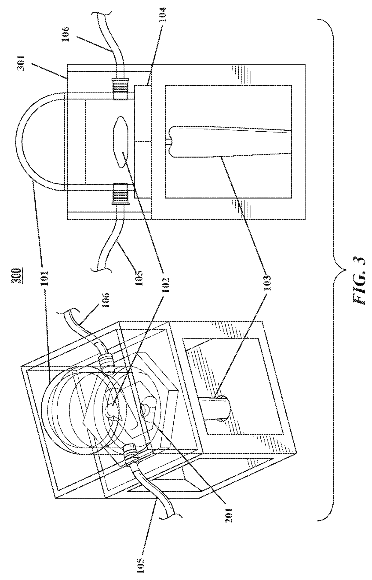
[0120]Bioreactors have conventionally been fabricated out of heavy plastic or glass, which preclude ultrasound imaging through the bioreactor walls. This is due to strong reflection coefficients of these materials. Therefore, a bioreactor chamber with an acoustically transparent window that allows ultrasound waves to penetrate into the media is provided. Particularly, a novel bioreactor design with an acoustically transparent floor made of thin, ultrasound-amenable material is produced and tested. The design is such that ultrasound penetrates into the bioreactor without the chamber having to be opened (thus preserving sterility), while maintaining all functionality of a traditional bioreactor including the ability to be sterilized with an autoclave.

[0121]Bioreactor Chamber.

[0122]The bioreactor chamber is constructed following a series of steps. First, a 0.125″ thick polycarbonate tube is chemically bonded ...


PUM

PropertyMeasurementUnit
lengthaaaaaaaaaa
thicknessesaaaaaaaaaa
thicknessaaaaaaaaaa

Abstract

Provided are systems for analyzing cellular distribution in an engineered tissue sample, which optionally is a bioprinted organ or tissue sample. In some embodiments, the systems include an ultrasound imaging system and a processing unit configured with software that permits analysis of images acquired from the engineered tissue sample in order to output desired characteristics thereof. In some embodiments, the systems also include a bioreactor for engineering a tissue sample and a pump configured to regulate flow of fluids and reagents into and out of the bioreactor, wherein at least one surface of the bioreactor includes a window that is acoustically transparent to ultrasound waves. Also provided are systems for analyzing cell distribution in an engineered tissue sample and methods for analyzing distribution of cells in an engineered tissue sample present within a bioreactor.

Description

CROSS REFERENCE TO RELATED APPLICATION[0001]This application claims the benefit of U.S. Provisional Application Ser. No. 62 / 383,068, filed Sep. 2, 2016, the disclosure of which is incorporated herein by reference in its entirety.GOVERNMENT INTEREST[0002]This invention was made with United States government support under Grant No. IIP-1533978 awarded by the National Science Foundation of the United States. The United States government has certain rights in the invention.TECHNICAL FIELD[0003]The presently disclosed subject matter relates generally to systems and methods for noninvasively evaluating engineered tissues and organs. In some embodiments, the presently disclosed subject matter relates to systems and methods for determining whether cells have localized and integrated into their intended location within a target tissue or organ.BACKGROUND[0004]For many diseases, organ transplant remains the only viable option for saving a patient's life. Unfortunately, there is a massive shor...

Claims


Application Information

Patent Timeline
Patent Type & Authority Applications(United States)
IPC IPC(8): G01N33/569G01N29/06G01N29/44B33Y40/00
CPCG01N33/56966G01N29/0654G01N29/44B33Y40/00G01N2291/02475B33Y30/00A61F2/06A61K35/00G01N29/00A61B8/08A61B8/4281A61B8/52
Inventor GESSNER, RYAN CHRISTOPHERDAYTON, PAUL ALEXANDERHARLACHER, MAX STEPHANBUTLER, JAMES OWENCZERNUSZEWICZ, TOMASZ JOSEPHO'CONNELL, GRAEME RAINIER
Owner THE UNIV OF NORTH CAROLINA AT CHAPEL HILL
Learn More