Pulse current generation circuit for neural stimulation, charge compensation circuit and method, and implantable electrical retina stimulator

Active Publication Date: 2019-07-25
SHENZHEN SIBIONICS CO LTD
View PDF0 Cites 0 Cited by
  • Summary
  • Abstract
  • Description
  • Claims
  • Application Information

AI Technical Summary

Benefits of technology

The present invention is related to a method for improving the resolution of retinal stimulation and generating a more accurate and effective sense of light. By stimulating bipolar cells in the retina, the stimulation resolution can be effectively improved. The invention utilizes a charge compensation circuit to actively compensate possible redundant net charge on the nerve tissue, ensuring safety and reliability of neural stimulation. The invention does not require a large capacitor with large occupied area, which makes it fully enhanced within a limited space.

Problems solved by technology

However, in conventional artificial retinas or artificial retinal systems such as implantable electrical retinal stimulators, the stimulation signals generated by the stimulation electrode generally are capable of stimulating only nerve cells (such as ganglion cells) on the surface of the retina, and cannot effectively stimulate retinal bipolar cells slightly away from the retina surface.
Therefore, the stimulation effect is seldom good.
In addition, in the existing neural stimulation devices such as artificial retina systems, the stimulating current generated for neural stimulation may not guarantee that the charge amount during one stimulation period falls within a safe range.
The nerve tissues (such as retinal ganglion cells or bipolar cells) being stimulated may therefore carry net charges, such as positive charges or negative charges, resulting in damage to the nerve tissues such as ganglion cells or bipolar cells in the retina.
However, in the field of neural stimulation, the space for the circuit is often limited, and a large capacitor occupying large area cannot be integrated into the circuit.
Therefore, the RC circuit cannot fully exert its function in charge balance.

Method used


Image

  • Pulse current generation circuit for neural stimulation, charge compensation circuit and method, and implantable electrical retina stimulator
  • Pulse current generation circuit for neural stimulation, charge compensation circuit and method, and implantable electrical retina stimulator
  • Pulse current generation circuit for neural stimulation, charge compensation circuit and method, and implantable electrical retina stimulator

Examples


first embodiment

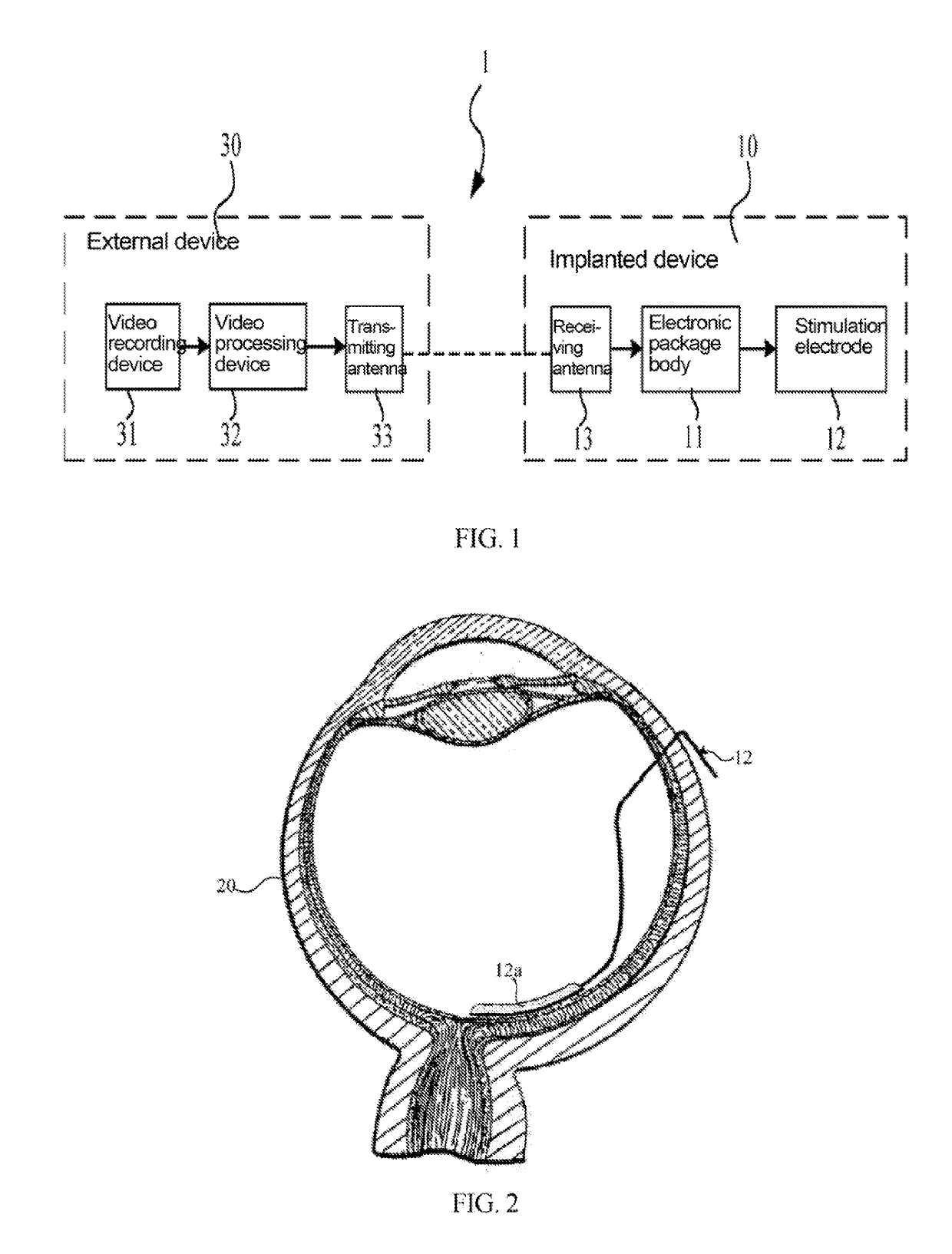
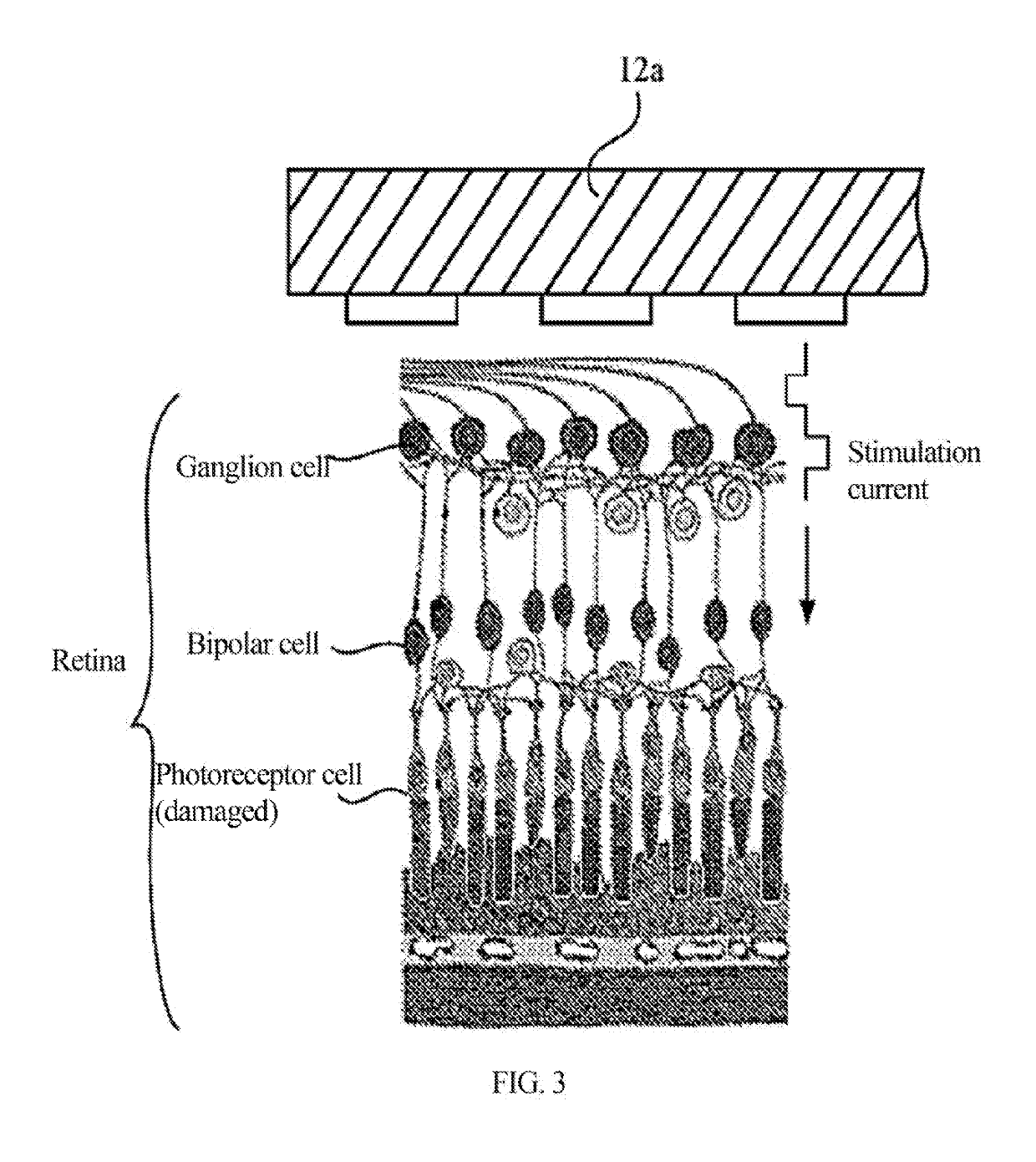
[0043]FIG. 1 is a structural schematic diagram showing an implantable electrical retina stimulator according to a first embodiment of the present invention. FIG. 2 is a schematic diagram showing the implantation of a stimulation electrode structure of the implantable electrical retina stimulator according to the first embodiment of the present invention into an eyeball. FIG. 3 is a partial schematic diagram showing the attachment of the stimulation electrode structure (a stimulation end) shown in FIG. 2 to the retina in the eyeball.

[0044]In the present embodiment, as shown in FIG. 1, the implantable electrical retina stimulator (sometimes referred to as an “artificial retina” or “artificial retina system”) 1 may include a part implanted into human body, i.e., an implanted device 10, and apart outside the body, i.e., an external device 30. In the implantable electrical retina stimulator according to the present embodiment, the implanted device 10 and the external device 30 may be cou...

second embodiment

[0090]FIG. 9 is a schematic diagram showing a circuit structure of a pulse current generation circuit according to the second embodiment of the present invention. FIG. 10 is a schematic diagram showing a circuit structure of a charge compensation circuit according to the second embodiment of the present invention. FIG. 11 is a schematic diagram showing a compensation pulse current according to the second embodiment of the present invention. FIG. 12 is a schematic diagram showing a circuit structure of the charge compensation circuit according to the second embodiment of the present invention.

[0091]The pulse current generation circuit 200 according to the second embodiment differs from the pulse current generation circuit 100 according to the first embodiment in that besides the analogue signal receiving device 101, the analogue-to-digital converter 102, the current signal controller 103 and the current generator 104 according to the first embodiment, the charge compensation circuit ...


PUM


Abstract

A pulse current generation circuit (100) for neural stimulation includes an analogue signal receiving device (101) for receiving an analogue signal; an analogue-to-digital converter (102) for converting the analogue signal into a digital control signal; a current signal controller (103) for producing, according to the digital control signal, pulse current parameters for generating bidirectional pulse current signals; and a current generator (104) for generating, according to the pulse current parameters, bidirectional pulse current signals for neural stimulation, and the current generator can generate pulse currents of different precisions according to the pulse current parameters. In addition, the present invention further relates to a charge compensation circuit, a charge compensation method, and an implantable electrical retina stimulator using the pulse current generation circuit or the charge compensation circuit.

Description

[0001]The present invention relates to a pulse current generation circuit, a charge compensation circuit, a charge compensation method, and an implantable electrical retina stimulator for neural stimulation.BACKGROUND OF INVENTION[0002]In the field of neural stimulation, nerve tissues respond to electrical stimulations from stimulation electrodes, thereby providing desired functions. For example, in the conventional vision repair system of artificial retina, in order to restore visual perception to the blind, it is generally necessary to put an implant into an eyeball of the blind. This implant functions as the photoreceptor cells that were impaired due to, for example, retinal pigmentation (RP) or age-related macular degeneration (AMD). If other functions of the visual pathway are retained, the stimulation electrodes in the implant can be used to stimulate neural pathways to restore partial vision for the blind.[0003]In an artificial retina system, an external camera outside the bo...

Claims


Application Information

Patent Timeline
IPC IPC(8): A61N1/36H03K3/017H03K5/02H03K5/00
CPCA61N1/36046H03K3/017H03K5/02H03K5/00006A61N1/36175A61N1/36142A61N1/36125A61N1/36157A61N1/0543H03K3/78
Inventor XIA, BINZHAO, YULIN, YUFANG, XIANWENCHEN, ZHI
Owner SHENZHEN SIBIONICS CO LTD
Why Eureka
Try Eureka