Internal protection circuit structure of photovoltaic module

Active Publication Date: 2019-07-18
TONGWEI SOLAR HEFEI
View PDF2 Cites 0 Cited by
  • Summary
  • Abstract
  • Description
  • Claims
  • Application Information

AI Technical Summary

Benefits of technology

The present invention is an internal encapsulation protection circuit for sliced photovoltaic modules that improves the practical utilization rate of the half-cell and enhances the operability of the process without additional investment costs. The unique design includes four diodes connected in bypass to effectively protect the half-cell and prevent a decrease in actual power generation. The levelized generation cost on the system side is reduced, and the half-cell module is compatible with the operational flow of the conventional photovoltaic module manufacturing process without extra fund investment to modify or upgrade the assembly line.

Problems solved by technology

With the accelerating energy consumption of conventional fossil fuels such as coal, oil, natural gas, etc., the eco-environment is continuously deteriorating.
Especially, due to the greenhouse gas emissions, the global climate change is getting worse and worse.
Therefore, the sustainable development of human society has been seriously threatened.
Considering the factors such as the compatibility of the assembly line of the manufacturing process of the conventional photovoltaic modules, the performance and reliability of the final product, etc., the above two kinds of internal protection circuit designs have some defects and drawbacks.
Two-third of the substrings of the solar cell (80 half-cells in total) are bypassed such that the power generation capacity thereof is lost.
In view of the electrical power output of the product, the levelized cost of electricity (LOCE) of the system side application of photovoltaic modules will be seriously affected.
Moreover, the risk of failure in the reliability test of the products will be greatly increased.
Therefore, the performance of the products is not stable.
Further, the compatibility of the method to the existing photovoltaic modules process assembly line is also relatively poor.
Such flow direction conflicts with the lateral flowing path and cannot be achieved in the conventional process assembly line.
Further, since there are four pairs of outgoing lines (eight lines in total), the processing operation cycle is seriously affected, raising the risk of defective products.

Method used


Image

  • Internal protection circuit structure of photovoltaic module

Examples


Embodiment Construction

[0023]The technical solutions in the embodiments of the present invention will be described clearly and completely hereinafter with reference to the accompanying drawings in the embodiments of the present invention. Apparently, the described embodiments are merely some but not all embodiments of the present invention. All other embodiments obtained by an ordinary person skilled in the art based on the embodiments of the present invention without creative efforts shall fall within the protective scope of the present invention.

[0024]Referring to FIGS. 1-2, the present invention provides a technical solution as below:

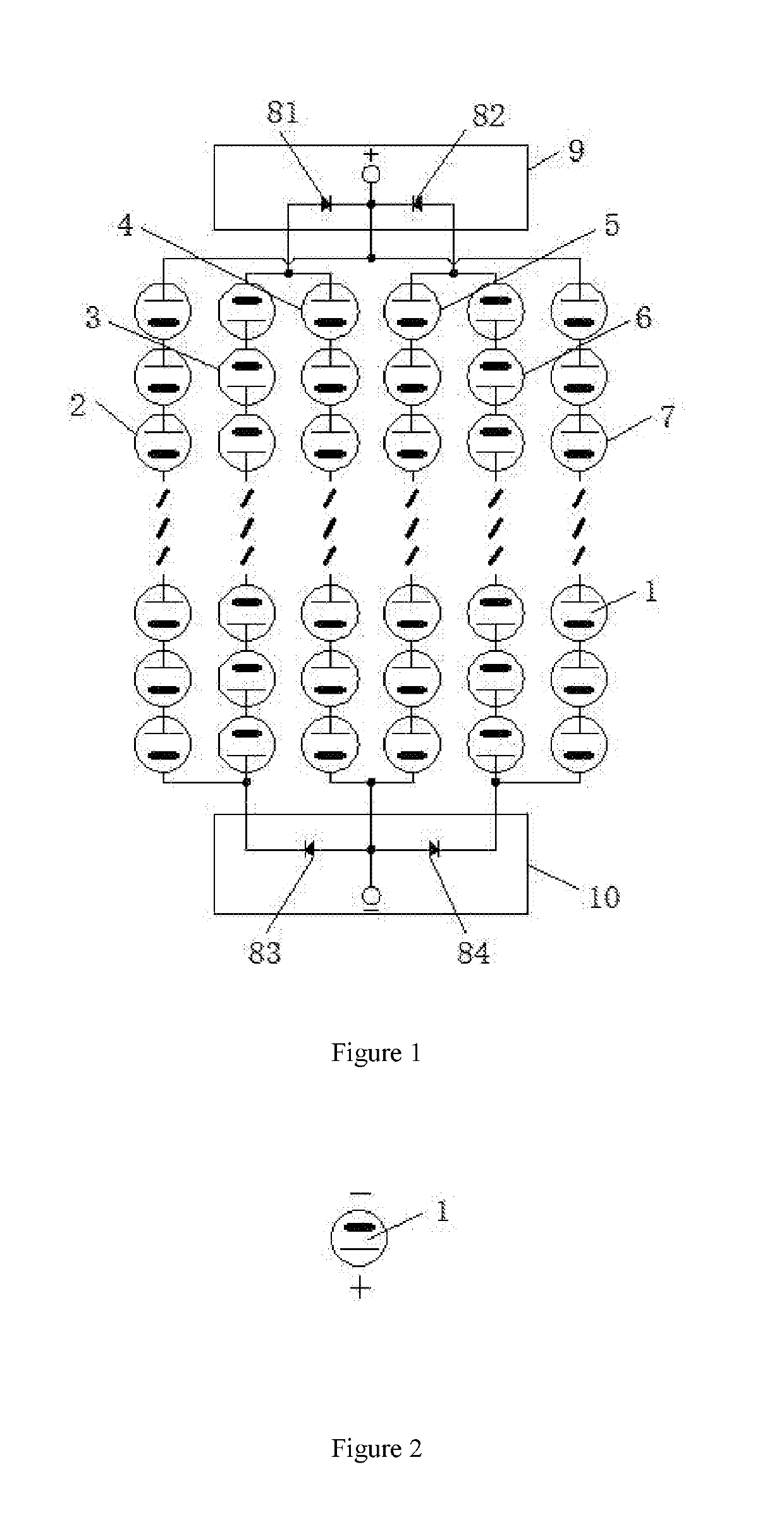
[0025]An internal protection circuit structure of a photovoltaic module includes a plurality of solar cells 1. As shown in FIG. 2 of the specification, a long-line end of solar cell 1 is a positive electrode and a short-line end is a negative electrode. The plurality of solar cells 1 are equally divided into six columns, i.e., first column 2, second column 3, third column ...


PUM


Abstract

An internal protection circuit structure of a photovoltaic module, which includes a plurality of solar cells including a first column, a second column, a third column, a fourth column, a fifth column, and a sixth column sequentially. Positive and negative electrodes of each column of the solar cells are sequentially connected in series to form a substring of the solar cell. The upper ends of the second column and the third column are connected to each other with a first diode connected in series to be pulled out as an outgoing terminal. The present invention uses a manner in which substrings are connected first in series and later in parallel, with four bypass diodes connected in the circuit. As such, the actual utilization ratio of the solar cell is improved.

Description

CROSS REFERENCE TO RELATED APPLICATIONS[0001]This application is the national phase entry of International Application No. PCT / CN2017 / 099227, filed on Aug. 28, 2017, the entire contents of which are incorporated herein by reference.TECHNICAL FIELD[0002]The present invention relates to the technical field of encapsulation of solar crystalline silicon sliced battery module, in particular to an internal protection circuit structure of a photovoltaic module.BACKGROUND[0003]With the accelerating energy consumption of conventional fossil fuels such as coal, oil, natural gas, etc., the eco-environment is continuously deteriorating. Especially, due to the greenhouse gas emissions, the global climate change is getting worse and worse. Therefore, the sustainable development of human society has been seriously threatened. Countries all around the world have formulated their own energy development strategies to cope with the limitations of conventional fossil fuel resources and the environmenta...

Claims


Application Information

Patent Timeline
IPC IPC(8): H01L31/0443H02S40/34
CPCH01L31/0443H02S40/34H01L31/044H01L31/02021Y02E10/50
Inventor JIANG, CHENGYINSUN, JUNZHOU, FUSHENXIE, TAIHONGXIE, YI
Owner TONGWEI SOLAR HEFEI
Why Eureka
Try Eureka