Optical deflection device and lidar apparatus
a technology of optical deflection device and lidar apparatus, which is applied in the direction of optical elements, instruments, and using reradiation, can solve the problems of short life, unstable mobile body, and unstable, and achieve the effect of avoiding enlargement or complication of a system and simple constitution
- Summary
- Abstract
- Description
- Claims
- Application Information
AI Technical Summary
Benefits of technology
Problems solved by technology
Method used
Image
Examples
fourth embodiment
of Emitter
[0093]FIG. 4(b) shows a fourth embodiment that the light deflection device is constituted as an emitter.
[0094]The light deflection device 1D in the fourth embodiment constitutes an emitter for guiding laser beams with wavelengths λ1-λ3 different from each other generated by the laser sources 3A-3C to one beam deflector 2 via one bus waveguide 6, and radiating the plural light beams at the emission angle corresponding to each wavelength, as is similar to the third embodiment.
[0095]The light deflection device 1C in the third embodiment is constituted that the wavelength λ generated by each laser source, and the refractive index n of each beam deflector are fixed, while the light deflection device 1D in the fourth embodiment is constituted that the wavelength λ and the refractive index n are variable.
[0096]The laser sources 3A-3C may be constituted that the plural laser sources for generating each wavelength are constituted by the same integrated circuit, the plural laser sou...
first embodiment
of Receiver
[0101]In the first embodiment, the receiver is constituted only by a beam deflector and a light detector. FIG. 5(a) shows the first embodiment in which the light deflection device is constituted as a receiver.
[0102]A light deflection device 1E in the first embodiment of the receiver includes plural beam deflectors 2A-2C, and plural light detectors 5A-5C connected to the beam deflectors 2A-2C via waveguides 4A-4C.
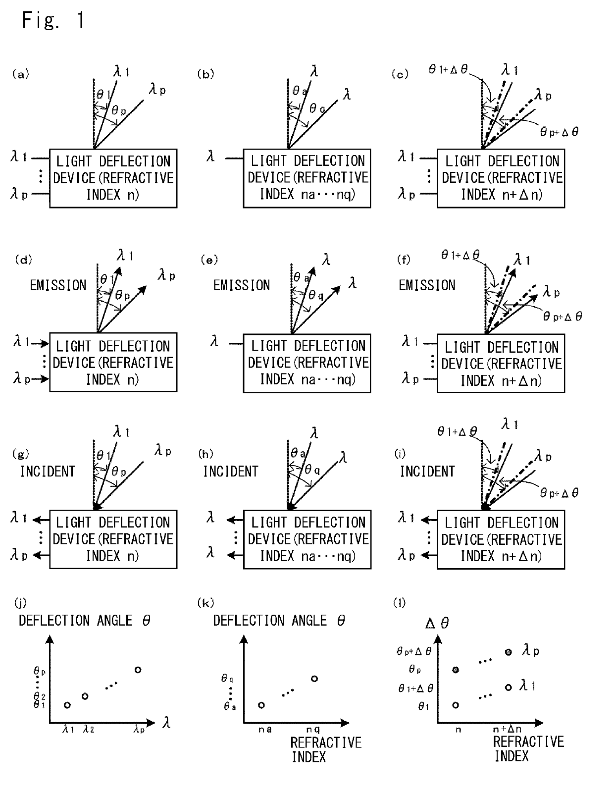
[0103]In the light deflection device 1E, the respective beam deflectors 2A-2C selectively, simultaneously and parallelly receives laser beams each having an incident angle defined by the wavelength of each laser beam and the refractive index of the beam deflector, among the laser beams with the respective wavelengths reaching from outside, and individually detect the received laser beams by the light detectors.
[0104]The beam deflectors 2A-2C may be configured so that the plural beam deflectors are formed on one substrate, and that the plural beam deflectors formed...
second embodiment
of Receiver
[0108]In the second embodiment, the beam deflector and the light detector are combined, and can be integrated. FIG. 5(b) shows the second embodiment in which the light deflection device is constituted as a receiver.
[0109]A light deflection device 1F in the second embodiment of the receiver includes plural beam deflectors 2A-2C, and plural light detectors 5A-5C connected to the beam deflectors 2A-2C via the waveguides 4A-4C. In FIG. 5(b), the waveguides 4A-4C are branched, the laser sources 3A-3C are connected to one branch end, and the light detectors 5A-5C are connected to the other branch end.
[0110]In the light deflection device 1F, the respective beam deflectors 2A-2C selectively, simultaneously and parallelly receive laser beams each having an incident angle defined by the wavelength of each laser beam and the refractive index of the beam deflector, among the laser beams with the respective wavelengths reaching from outside, and individually detect the received laser ...
PUM
| Property | Measurement | Unit |
|---|---|---|
| distance | aaaaa | aaaaa |
| refractive index | aaaaa | aaaaa |
| diameter | aaaaa | aaaaa |
Abstract
Description
Claims
Application Information
 - R&D Engineer
- R&D Manager
- IP Professional
- Industry Leading Data Capabilities
- Powerful AI technology
- Patent DNA Extraction
Browse by: Latest US Patents, China's latest patents, Technical Efficacy Thesaurus, Application Domain, Technology Topic, Popular Technical Reports.
© 2024 PatSnap. All rights reserved.Legal|Privacy policy|Modern Slavery Act Transparency Statement|Sitemap|About US| Contact US: help@patsnap.com


