Time-of-flight distance measurement device
a distance measurement and time-of-flight technology, applied in distance measurement, instruments, surveying and navigation, etc., can solve the problems of interference between received signals and difficult to differentiate between near and distant targets, and achieve the effect of removing the influence of aliasing
- Summary
- Abstract
- Description
- Claims
- Application Information
AI Technical Summary
Benefits of technology
Problems solved by technology
Method used
Image
Examples
first embodiment
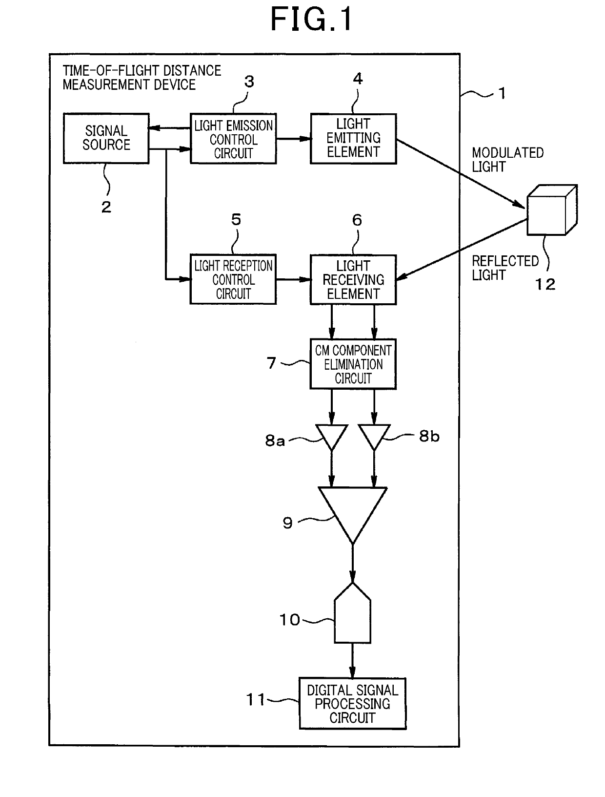
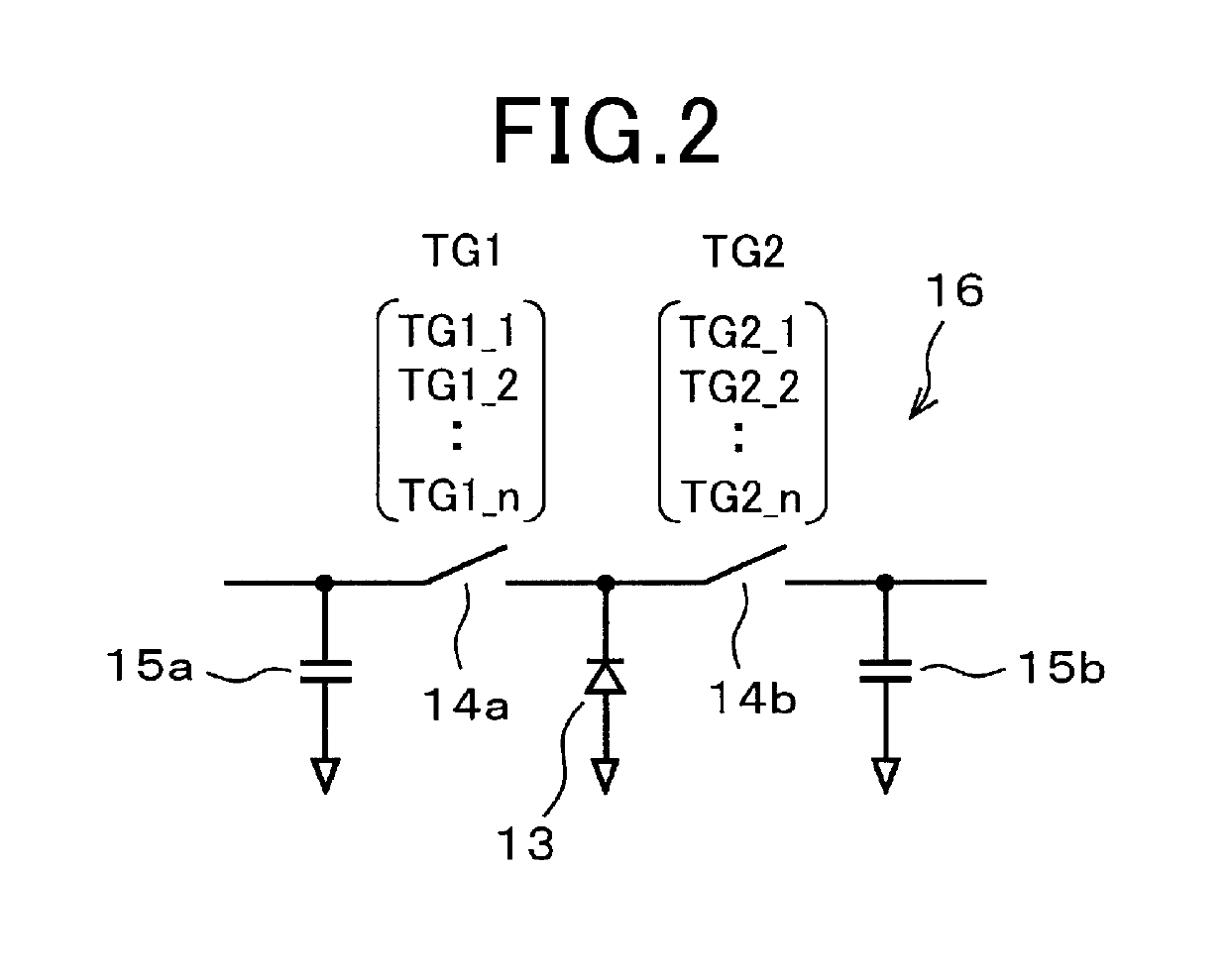
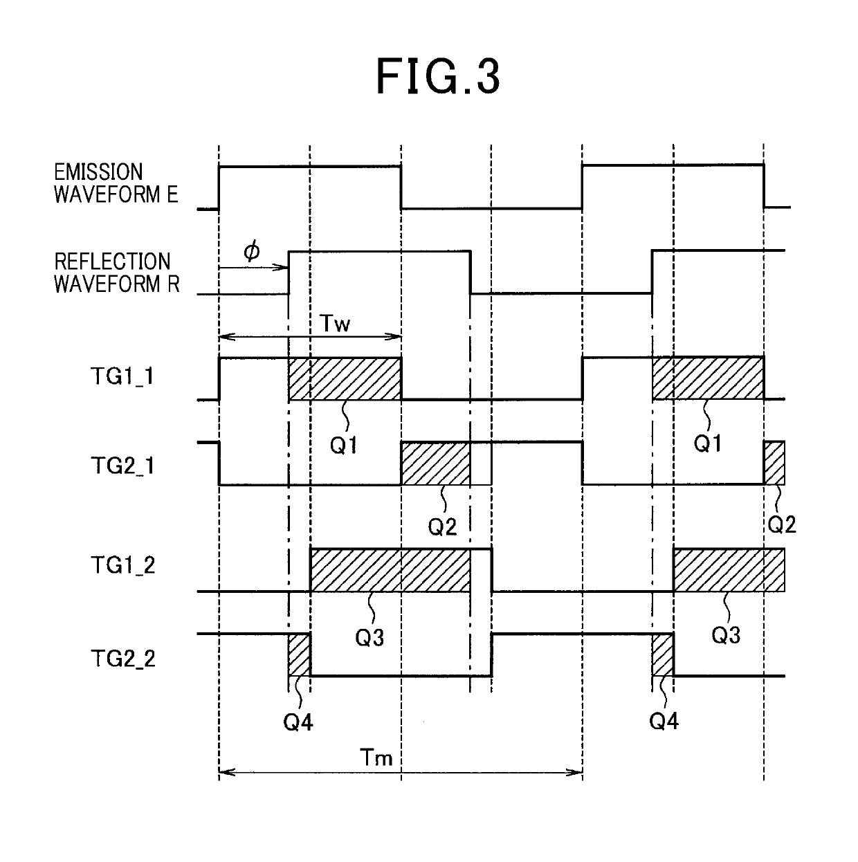
[0032]FIGS. 1 to 5 are illustrative diagrams of a first embodiment. A time-of-flight distance measurement device (hereinafter, simply called distance measurement device) 1 includes a signal source 2, a light emission control circuit 3 as a light emission control unit, a light emitting element 4, a light reception control circuit 5 as a light reception control unit, a light receiving element 6, a common-mode (CM) component elimination circuit 7, buffers 8a and 8b, a difference detection circuit 9, an AD conversion circuit 10, and a digital signal processing circuit 11. The digital signal processing circuit 11 acts as a distance measurement unit, a signal processing unit, a discharge control unit, an extension setting unit, and a comparison unit. The distance measurement device 1 is configured to calculate the distance from the subject device to a target 12. The target 12 is a person, an object, another vehicle such as a preceding vehicle, an obstacle on a road, a wall as a roadside o...
second embodiment
[0068]FIG. 6 is a supplemental illustrative diagram of a second embodiment. In the first embodiment, the length of one period of the sequence SQ conforms to the length of the sub sequence SUS. In the second embodiment, the length of the sub sequence SUS is changed from the length of one period of the sequence SQ.
[0069]The period of the pulse pattern and the length of the sub sequence SUS can be set to satisfy the relationship the length of the sub sequence SUS (=(the period of the modulation frequency f1)×(the number N of pulse patterns))2). FIG. 6 illustrates a timing Ta for forward polarity change by solid lines and a timing Tb for reverse polarity change by broken lines. As illustrated in FIG. 6, the relationship between the length of the sub sequence SUS and the modulation frequencies f1 and f2 can be set in any manner as far as the foregoing condition is satisfied.
[0070]In the second embodiment, making such settings creates the need to increase the measurement accuracy at the m...
third embodiment
[0071]FIG. 7 is a supplemental illustrative diagram of a third embodiment. In the first embodiment, the basic sequence SQ is applied to the distance measurement process using the modulation frequency f2 on the condition that the errors caused by the interference from other sensors are permissible in the distance measurement process using the modulation frequency f2. Alternatively, as in the distance measurement process at the modulation frequency f1 in the first embodiment, the sub sequence SUS (f2) with a plurality of number of repetitions of a pulse pattern may be used such that the polarity is changed in the forward or reverse direction at random with a ½ probability at each execution of the sub sequence SUS (f2). In the example of FIG. 7, timings Ta1 and Ta2 for forward polarity change are indicated by solid lines and timings Tb1 and Tb2 for reverse polarity change are indicated by broken lines.
[0072]The light emission control circuit 3 uses the sub sequence SUS (f2) with M repe...
PUM
 Abstract
Description
Claims
Application Information
 - R&D
- Intellectual Property
- Life Sciences
- Materials
- Tech Scout
- Unparalleled Data Quality
- Higher Quality Content
- 60% Fewer Hallucinations
Browse by: Latest US Patents, China's latest patents, Technical Efficacy Thesaurus, Application Domain, Technology Topic, Popular Technical Reports.
© 2025 PatSnap. All rights reserved.Legal|Privacy policy|Modern Slavery Act Transparency Statement|Sitemap|About US| Contact US: help@patsnap.com


