
Redundantly Operable Industrial Communication System, Method for Operation Thereof and Radio subscriber Station

Active Publication Date: 2019-05-23
SIEMENS AG
View PDF0 Cites 5 Cited by
  • Summary
  • Abstract
  • Description
  • Claims
  • Application Information

AI Technical Summary

Benefits of technology

The present invention provides an industrial communication system with wireless transmission paths that is reliable and efficient in using radio resources. The system ensures that the two radio stations do not connect to the same radio base station simultaneously during roaming operations. The radio stations use mutually redundant data frames with unique sequence numbers to coordinate among each other and avoid a plurality of stations connecting to the same radio base station simultaneously. This system optimizes the use of radio resources and ensures reliable communication.

Problems solved by technology

Interruptions in communication connections between industrial automation devices or computer units of an industrial automation system are extremely problematic.
In addition to a loss of information, this may result, for example, in disadvantageous repetition of transmission of measurement or diagnostic results or service requests.
This causes additional utilization of communication connections of the industrial automation system which, in turn, may result in further system faults or errors.
In addition, untransmitted or incompletely transmitted messages may prevent an industrial automation system from changing to or remaining in a safe operating state, for example.
In the worst-case scenario, the result may be failure of a complete production installation and costly production downtime.
A particular problem regularly results in industrial automation systems from message traffic with a comparatively large number of, but relatively short, messages, thus intensifying the above problems.

Method used


Image

  • Redundantly Operable Industrial Communication System, Method for Operation Thereof and Radio subscriber Station
  • Redundantly Operable Industrial Communication System, Method for Operation Thereof and Radio subscriber Station
  • Redundantly Operable Industrial Communication System, Method for Operation Thereof and Radio subscriber Station

Examples


Embodiment Construction

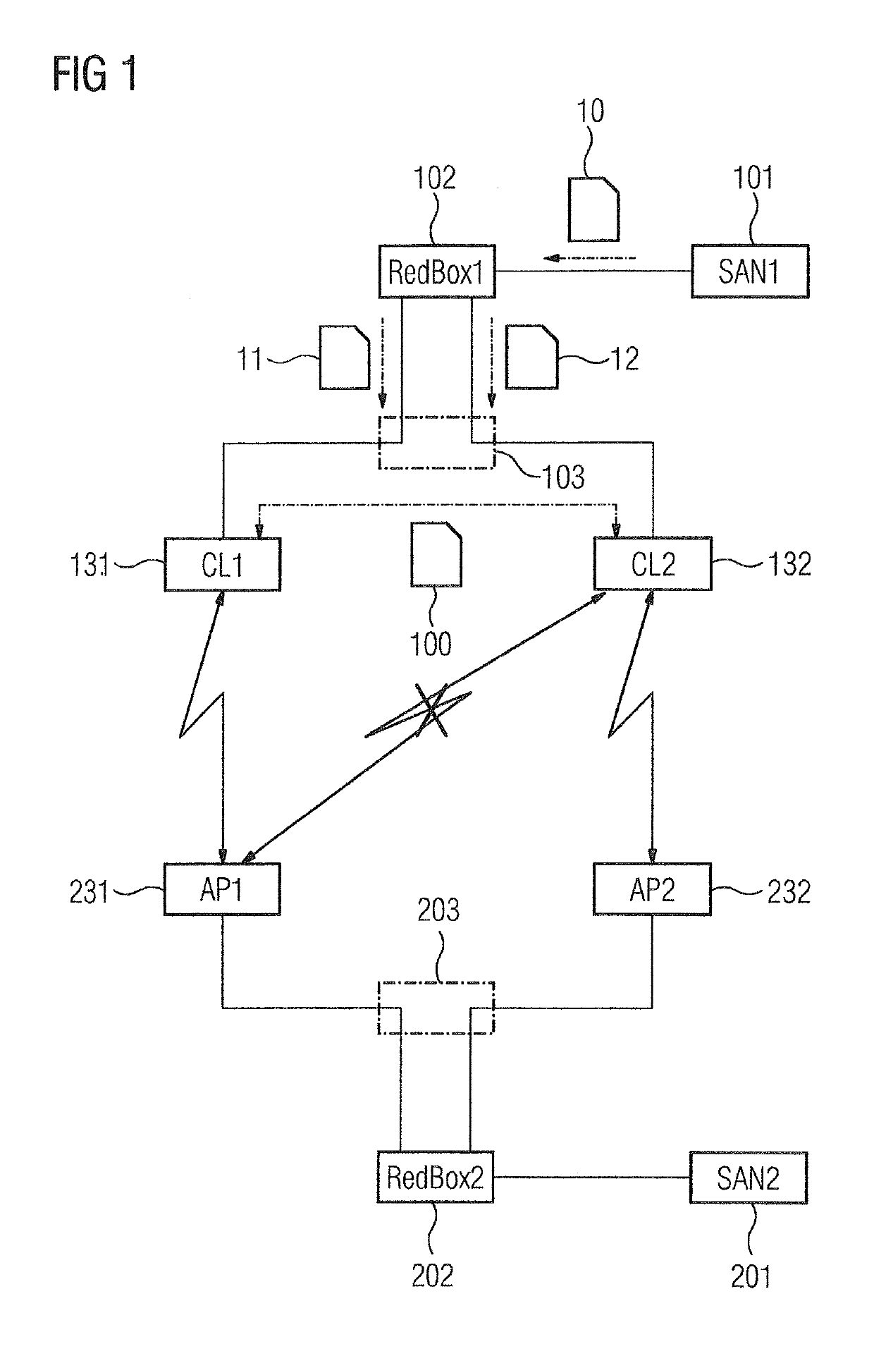
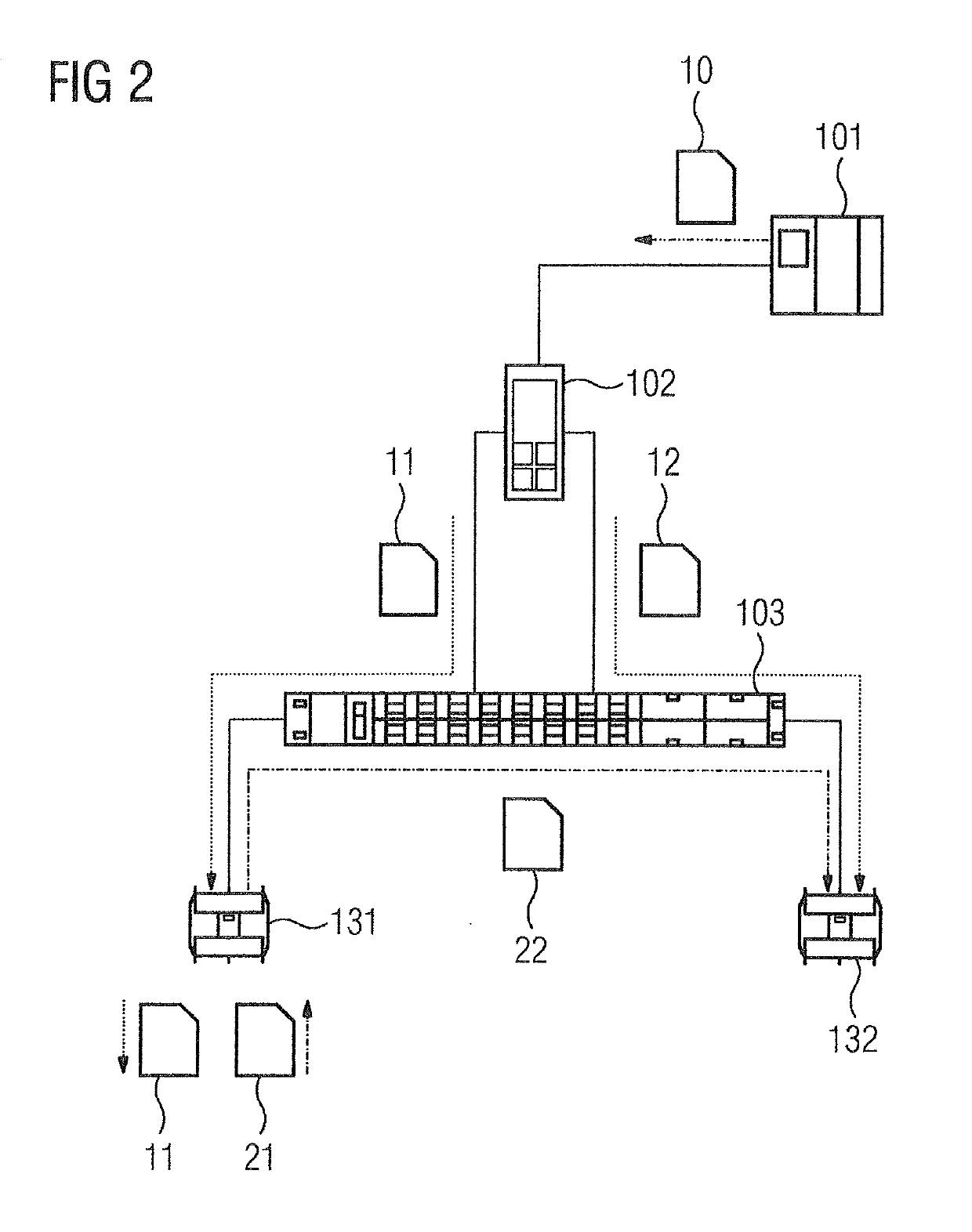
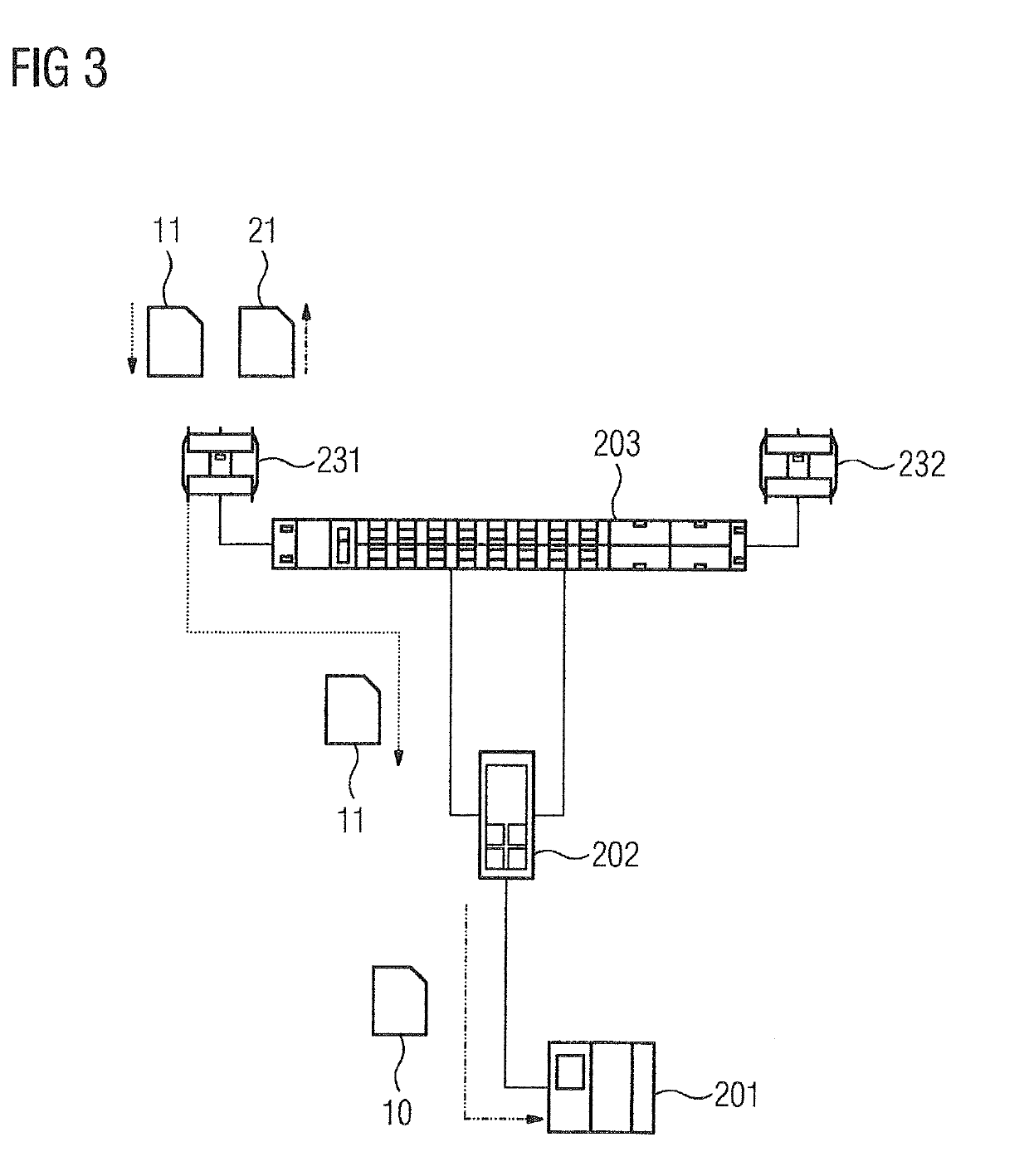
[0026]The industrial communication system illustrated in FIG. 1 comprises a first PRP RedBox 102 and a second PRP RedBox 202 each having at least three communication network connections. In the present exemplary embodiment, the first PRP RedBox 102 is respectively connected indirectly to a WLAN subscriber station 131, 132 via its first and second communication network connections. In a corresponding manner, the second PRP RedBox 202 is respectively connected indirectly to a WLAN base station 231, 232 via its first and second communication network connections. The two PRP RedBoxes 102, 202 each have an interlink port as a third communication network connection.

[0027]In the present exemplary embodiment, a Supervisory Control and Data Acquisition (SCADA) system 101 is connected to the interlink port of the first PRP RedBox 102 on the control system level. In contrast, a sensor and actuator system 201 of an industrial automation system is connected to the interlink port of the second PR...


PUM


Abstract

A radio communication system for an industrial automation system in which at least a first and a second communication device are redundantly linked to an industrial communication network, wherein the first and second communication devices are each connected indirectly or directly to a particular first radio subscriber station or radio base station and to a particular second radio subscriber station or radio base station via the first communication network connection and via the second communication network connection of the communication devices, where the radio subscriber stations interchange messages about available radio base stations among one another and use the messages to coordinate which of the radio subscriber stations has exclusive authorization for a radio link to a selected radio base station at present or within a definable period.

Description

CROSS-REFERENCE TO RELATED APPLICATIONS[0001]This is a U.S. national stage of application No. PCT / EP2017 / 056359 filed Mar. 17, 2017. EP Application No. 16167676 filed Apr. 29, 2016, the entire content of which is hereby incorporated by reference.BACKGROUND OF THE INVENTION1. Field of the Invention[0002]The present invention relates to a radio transceiver station, a redundantly operable industrial communication system and method for operating the communication system.2. Description of the Related Art[0003]An industrial automation system usually comprises a multiplicity of automation devices networked to one another via an industrial communication network and is used to control or regulate installations, machines or devices within the scope of manufacturing or process automation. On account of time-critical framework conditions in technical systems automated using industrial automation systems, real-time communication protocols, such as PROFINET, PROFIBUS or real-time Ethernet, are pr...

Claims


Application Information

Patent Timeline
IPC IPC(8): H04W12/08H04L12/40H04L12/46
CPCH04W12/08H04L12/40182H04L12/4641H04W88/06H04W88/08H04L49/00
Inventor MULLER, JORG
Owner SIEMENS AG
Learn More