Eureka AIR delivers breakthrough ideas for toughest innovation challenges, trusted by R&D personnel around the world.

Capacitively coupled chopper amplifier

a chopper amplifier and capacitor technology, applied in differential amplifiers, amplifiers with semiconductor devices/discharge tubes, amplifiers, etc., can solve problems such as increasing gain errors, adding noise, and potential output errors with settling

Active Publication Date: 2019-05-23
TEXAS INSTR INC
View PDF0 Cites 3 Cited by
  • Summary
  • Abstract
  • Description
  • Claims
  • Application Information

AI Technical Summary

Benefits of technology

The patent describes a new design for a chopper amplifier that uses six phases instead of two. These phases are used to address issues with conventional amplifiers. Two phases are used to equalize the feedback capacitors and set the input common mode value. Two phases are also used for passive transfer of input charge to the zeroed feedback capacitors. The final two phases are used for chopping and amplification. This design solves issues with settling and enables the amplifier to operate at a higher frequency.

Problems solved by technology

However, the simplistic capacitively coupled chopper amplifiers have problems relating to lack of an input common mode to the amplifier input and some potential output errors with settling.
Approaches to solve the common mode issue generally result in adding noise and increasing the gain error or increasing the common mode settling time.
This means that the improved design can only be used in very low precision environments and or at lower frequencies.

Method used


Image

  • Capacitively coupled chopper amplifier
  • Capacitively coupled chopper amplifier
  • Capacitively coupled chopper amplifier

Examples


Embodiment Construction

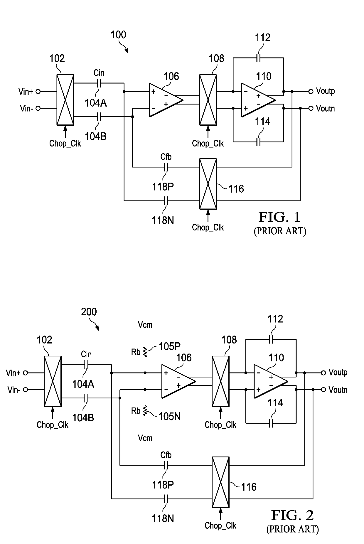
[0020]Referring now to FIG. 1, a simple capacitively coupled chopper amplifier 100 according to the prior art is illustrated. Vin+ and Vin− signals are provided to a first chopping switch 102. The outputs of the first chopping switch 102 are provided to series capacitors 104A and 104B. The series capacitor 104A is connected to the plus or noninverting input of a first differential amplifier 106. The series capacitor 104B is connected to the minus or inverting input of the first amplifier 106. The differential inverting and non-inverting outputs of the first amplifier 106 are provided to first and second inputs of a second chopping switch 108. The first and outputs of the second chopping switch 108 are provided to the inverting and noninverting inputs of a second differential amplifier no, respectively. A feedback capacitor 112 is connected between the positive output of the second amplifier no and the inverting input of the second amplifier no. A feedback capacitor 114 is connected ...


PUM


Abstract

A six phase capacitively coupled chopper amplifier. Two phases provide a zeroing phase to zero the feedback capacitors and set the input common mode value. Two phases provide a passive transfer of an input charge from the input capacitors to the zeroed feedback capacitors. The final two phases are chopping and amplification phases. The zeroing phases address the input common mode without the need for biasing resistors. The passive transfer phases resolve the glitching that occurs if the feedback capacitors have to be recharged on each cycle of the chopping clock. Resolving the glitching and the charge time allows the frequency of the amplifier to increase.

Description

CROSS REFERENCE TO RELATED APPLICATIONS[0001]This application claims the benefit under 35 U.S.C. § 119(e) of U.S. Provisional Patent Application Ser. No. 62 / 589,106, filed Nov. 21, 2017, titled “Capacitive Coupled Amplifier Using Zeroing and Passive Charge Transfer,” which is hereby incorporated by reference as if reproduced in its entirety.BACKGROUND1. Field[0002]The field relates to capacitively coupled chopper amplifiers.2. Description of the Related Art[0003]There are many fields that need amplifiers that can measure precise current from the nano-Amp range to hundreds of Amps from a bus voltage which can be much higher or lower than the supply of the amplifier. These fields include various biomedical applications and electric power applications. For precise measurement, it is important that the amplifiers that are used have very low bias current, low offset voltage and very high common mode rejection ratio. To this end, capacitively coupled chopper amplifiers are commonly used. ...

Claims


Application Information

Patent Timeline
Patent Type & Authority Applications(United States)
IPC IPC(8): H03F1/26H03F3/45
CPCH03F1/26H03F3/45071H03F2200/129H03F2200/267H03F2200/156H03F2203/45151H03F2200/271H03F2200/459H03F2200/231H03F2200/252H03F2200/414H03F2200/421H03F2203/45116H03F2203/45512H03F2203/45536H03F3/387H03F3/45475
Inventor TRIFONOV, DIMITARDASH, BIRAJA PRASADBALASINGAM, RAVINTHIRAN
Owner TEXAS INSTR INC
Why Eureka
Eureka Blog
Learn More