
Solid-state lighting lamp

Active Publication Date: 2019-05-23
SIGNIFY HLDG BV
View PDF12 Cites 2 Cited by
  • Summary
  • Abstract
  • Description
  • Claims
  • Application Information

AI Technical Summary

Benefits of technology

This patent describes a new design for SSL lamps that improves their visual appearance and makes the internal structure, such as the heat spreader, less of a concern from a visual design perspective. This is achieved through the use of optical means, such as optical foils or plastic optical foils, which can be integrated into existing types of SSL lamps without needing to modify or add to the manufacturing process. The optical means can make the internal member appear thinner, longer, or flatter, and can even render it nearly invisible to an observer. Additionally, the patent describes how the end cap can be connectable to an Edison screw socket, making the SSL lamp suitable for retrofitting applications. The glass tube may extend beyond a top of the heat spreader, making the SSL lamp compact, robust, and easy to manufacture.

Problems solved by technology

It may then be possible to give the heat spreader a shape that optimizes technical performance or production costs, even though that shape is not visually appealing, and / or to make the heat spreader of a material that represents the best choice from a technical or an economic perspective, even though that material is a poor choice from a visual design perspective.

Method used


Image

  • Solid-state lighting lamp
  • Solid-state lighting lamp
  • Solid-state lighting lamp

Examples


Embodiment Construction

[0030]The present invention will now be described more fully hereinafter with reference to the accompanying drawings, in which currently preferred embodiments of the invention are shown. This invention may, however, be embodied in many different forms and should not be construed as limited to the embodiments set forth herein; rather, these embodiments are provided for thoroughness and completeness, and fully convey the scope of the invention to the skilled person.

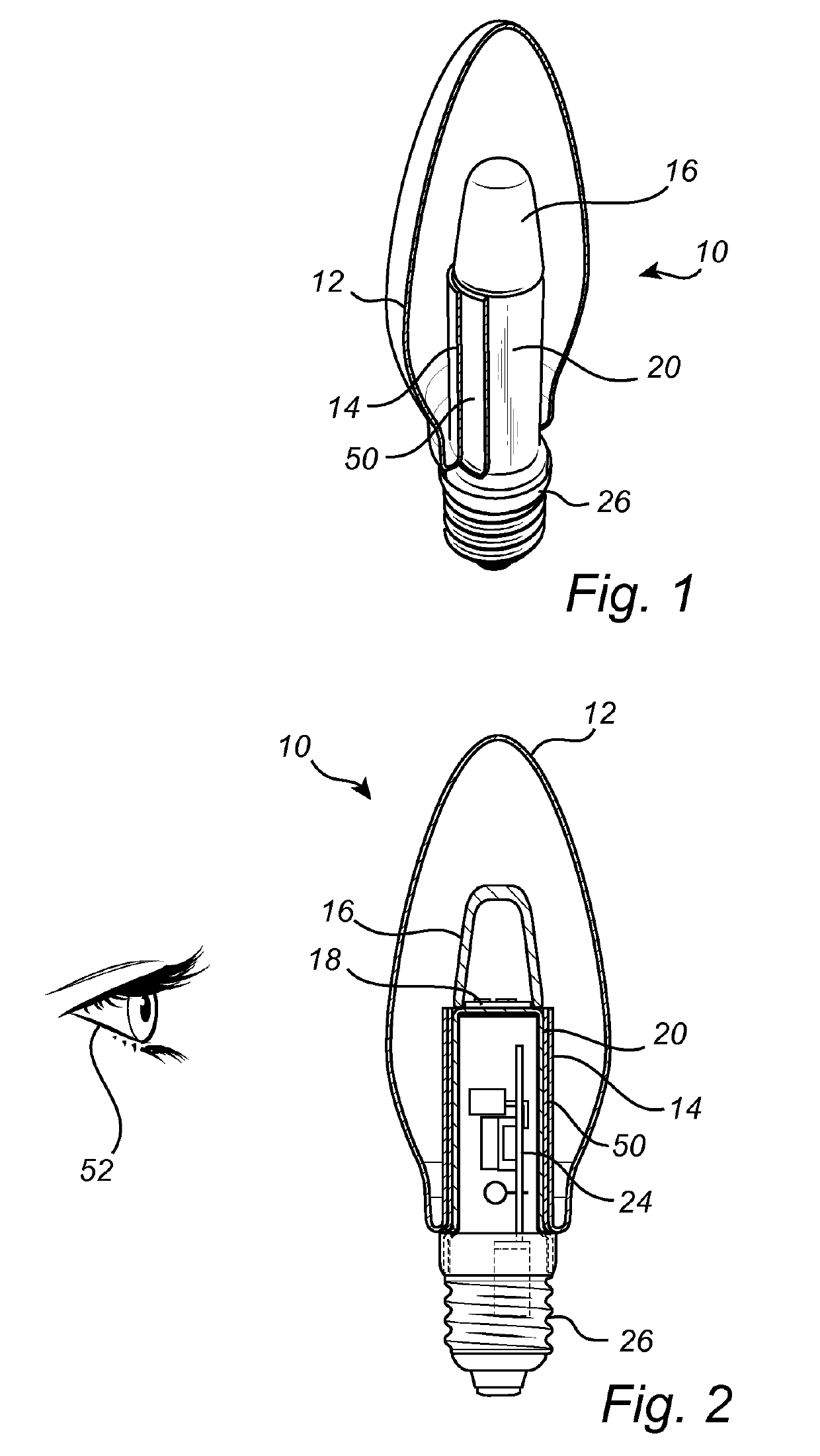
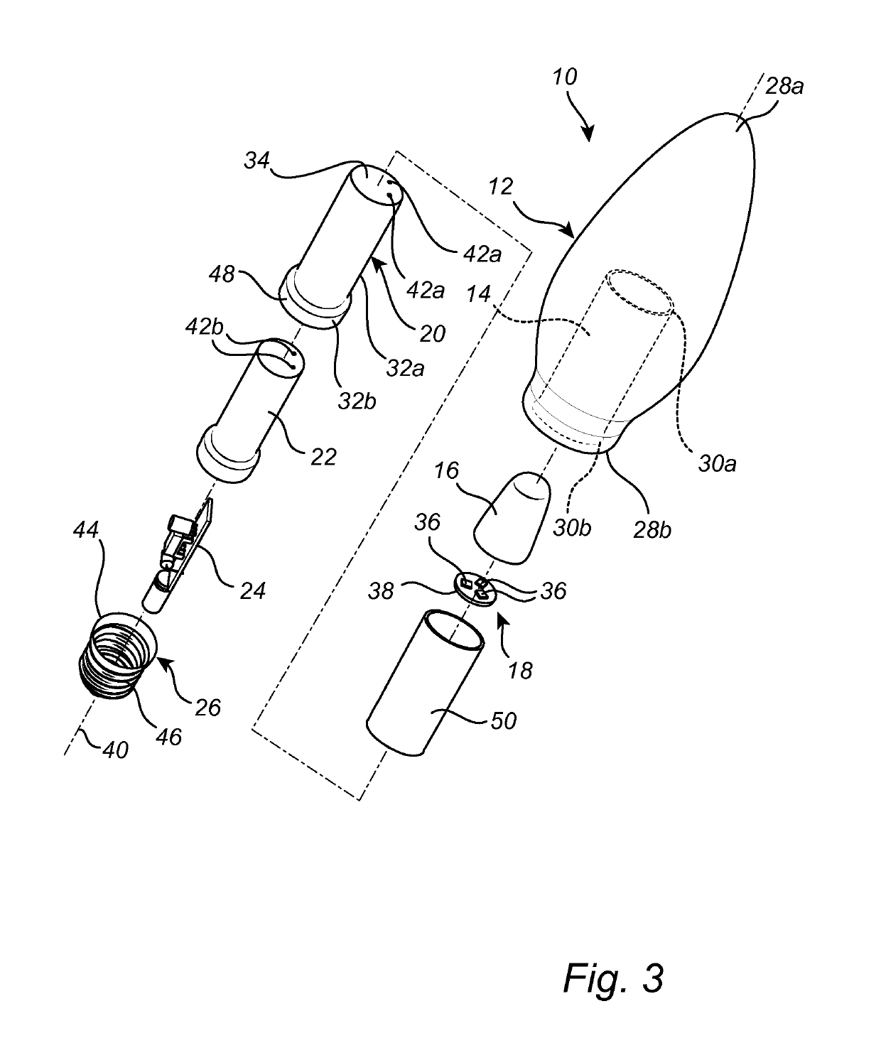
[0031]FIGS. 1 to 3 illustrate an SSL lamp 10 according to an embodiment of the present invention. The SSL lamp 10 in FIGS. 1 to 3 is an LED (light-emitting diode) candle lamp. The SSL lamp 10 may be a retrofit lamp.

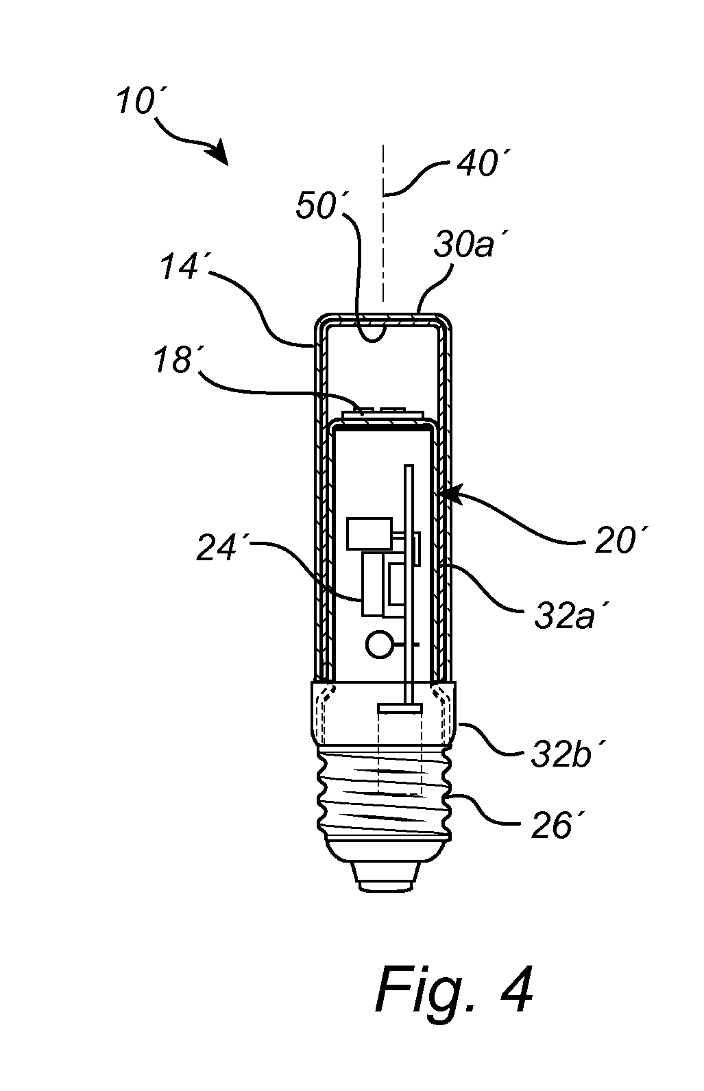
[0032]From top to bottom as seen in FIG. 3, the SSL lamp 10 comprises a glass bulb 12 with a glass tube 14, an optical part 16, an SSL unit 18, a heat spreader 20, a driver insulator 22, a driver 24, and an end cap 26. The SSL unit 18 and the heat spreader 20 may together be referred to as an internal member of t...


PUM


Abstract

A solid-state lighting lamp (10) is disclosed. The solid-state lighting lamp (10) comprises a glass tube (14), an internal member at least partly arranged inside the glass tube (14), and optical means (50) arranged on the glass tube (14), completely covering an inner surface of the glass tube (14) and adapted to at least partly cloak the internal member.

Description

FIELD OF THE INVENTION[0001]The present invention relates to a lamp based on SSL (solid-state lighting) technology.BACKGROUND OF THE INVENTION[0002]Visual aesthetics influence consumers' buying decisions for a wide range of products, including lamps. Lamps based on SSL technology typically have components that are difficult to integrate into the overall design of the lamp in an aesthetically pleasing way. For example, the lamp disclosed in CN 103982872 A has a conspicuous insertion portion which sticks into the glass bulb and which reduces the visual appeal of the lamp.[0003]Meeting consumers' visual design preferences without compromising performance and cost is associated with many technical challenges. There is a need for further efforts aimed at addressing those challenges. In particular, there is a need to find ways to make visually unattractive lamp components less conspicuous.[0004]In WO2015 / 177038 a solid state lighting device is disclosed with an inner envelope and an outer...

Claims


Application Information

Patent Timeline
IPC IPC(8): F21K9/232F21V3/02F21V3/06F21V29/70F21K9/60F21V23/00
CPCF21K9/232F21V3/02F21V3/061F21V29/70F21K9/60F21V23/006F21Y2113/13F21Y2115/10F21K9/90F21V23/009
Inventor GIELEN, VINCENT STEFAN DAVIDANSEMS, JOHANNES PETRUS MARIA
Owner SIGNIFY HLDG BV
Learn More