Solid-state lighting lamp

Active Publication Date: 2021-02-23
SIGNIFY HLDG BV
View PDF23 Cites 0 Cited by
  • Summary
  • Abstract
  • Description
  • Claims
  • Application Information

AI Technical Summary

Benefits of technology

[0009]The optical means are adapted to alter the visibility of the internal member, for example by making it appear thinner, longer or flatter. The optical means may be adapted to render the internal member nearly invisible to an observer. The internal member will therefore not disturb, or at least to a lesser extent disturb, the visual aesthetics of the SSL lamp, whereby the visual appearance of the SSL lamp is improved. Further, the fact the optical means make the internal structure less of a concern from a visual design perspective implies more freedom of choice for the manufacturer of the SSL lamp. For instance, consider the example case where the internal member is a heat spreader. It may then be possible to give the heat spreader a shape that optimizes technical performance or production costs, even though that shape is not visually appealing, and / or to make the heat spreader of a material that represents the best choice from a technical or an economic perspective, even though that material is a poor choice from a visual design perspective.
[0011]The optical means may be arranged between the internal member and the glass tube. It is possible to achieve a strong “cloaking effect” by arranging the optical means in this way.
[0013]The optical means may be an optical foil. By an “optical foil” is meant a thin foil, film, sheet, or the like, which is adapted to affect light incident thereon in some way, for example by being provided with an interior structure affecting how light travels inside the foil and / or surface elements, such as micro prisms or the like, affecting light how light is reflected and / or refracted at the surface of the foil. Optical foils can provide a strong “cloaking effect.” Further, the thinness of the optical foil facilitates its integration into existing types of SSL lamps. The manufacturing process does not become more complicated, and the other components do not need to be modified, or at least only marginally so. Further, the optical foil can be inexpensive to manufacture, so it typically represents a very small part of the total cost of the SSL lamp.
[0016]The optical means may be a plastic optical foil. Plastic optical foils typically offer a high level of technical performance while being relatively inexpensive to manufacture.
[0021]The end cap may be connectable to an Edison screw socket. Such an end cap can make the SSL lamp especially suitable for retrofitting applications.
[0023]The glass tube may extend beyond a top of the first section of the cylindrical heat spreader as seen along a longitudinal axis of the SSL lamp in a direction away from the end cap. The glass tube may be longer than the first section of the cylindrical heat spreader as measured along a longitudinal axis of the SSL lamp. With such a glass tube it is, for example, not necessary to provide the SSL lamp with a glass bulb, and such SSL lamps can be particularly compact and robust. They are also easy to manufacture using simple machines and tools.

Problems solved by technology

It may then be possible to give the heat spreader a shape that optimizes technical performance or production costs, even though that shape is not visually appealing, and / or to make the heat spreader of a material that represents the best choice from a technical or an economic perspective, even though that material is a poor choice from a visual design perspective.

Method used


Image

  • Solid-state lighting lamp
  • Solid-state lighting lamp
  • Solid-state lighting lamp

Examples


Embodiment Construction

[0031]The present invention will now be described more fully hereinafter with reference to the accompanying drawings, in which currently preferred embodiments of the invention are shown. This invention may, however, be embodied in many different forms and should not be construed as limited to the embodiments set forth herein; rather, these embodiments are provided for thoroughness and completeness, and fully convey the scope of the invention to the skilled person.

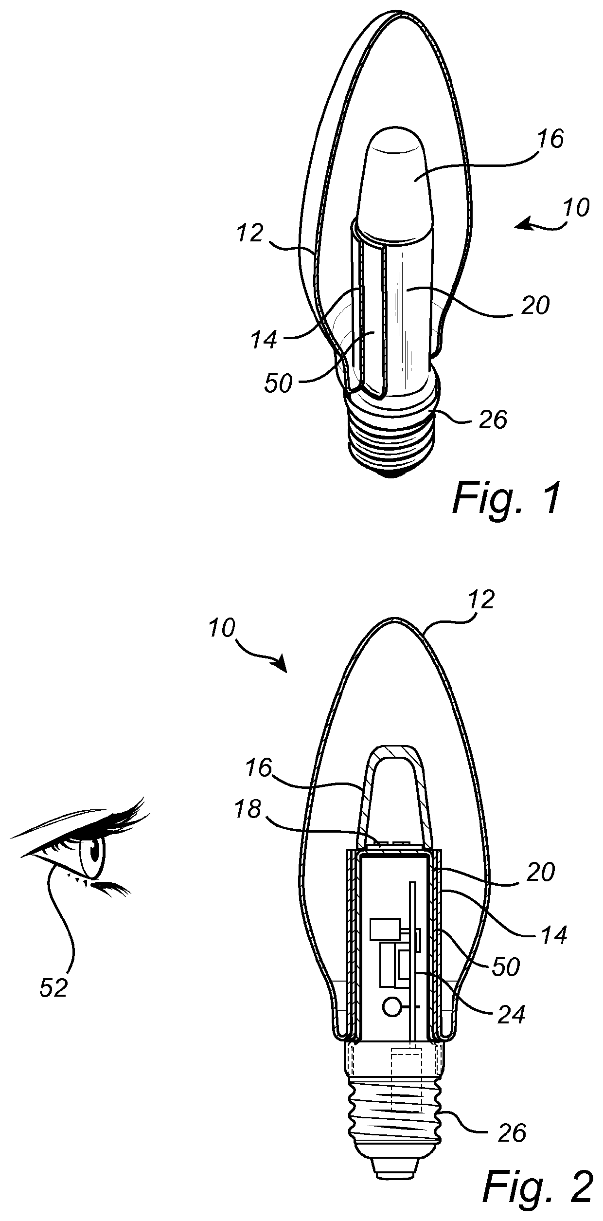
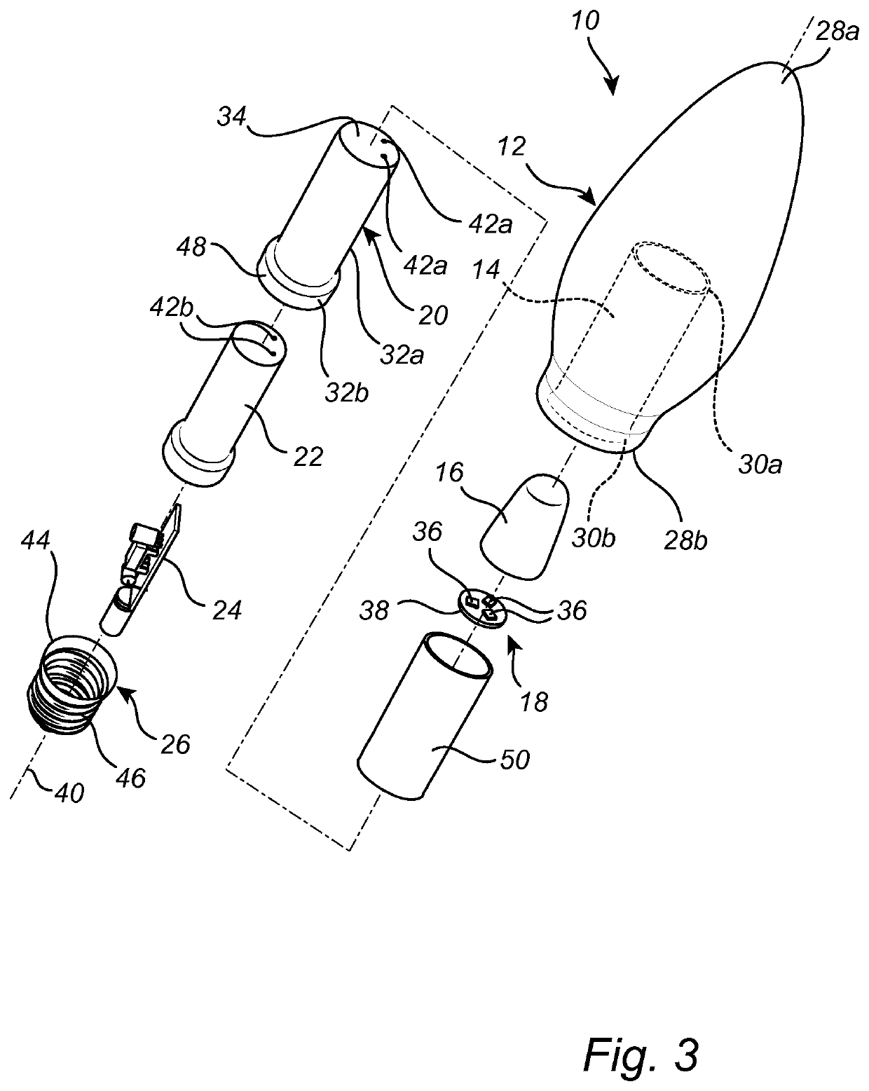
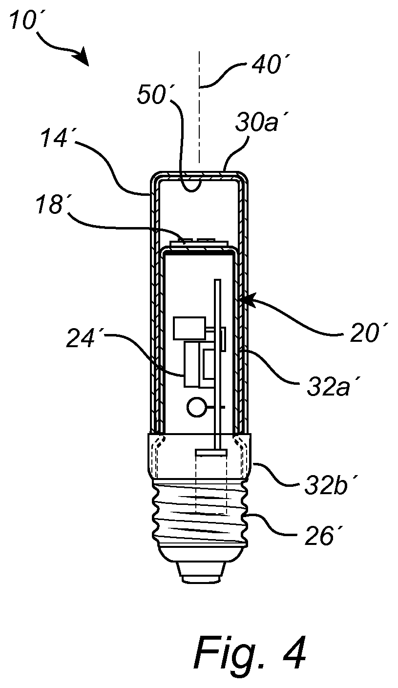
[0032]FIGS. 1 to 3 illustrate an SSL lamp 10 according to an embodiment of the present invention. The SSL lamp 10 in FIGS. 1 to 3 is an LED (light-emitting diode) candle lamp. The SSL lamp 10 may be a retrofit lamp.

[0033]From top to bottom as seen in FIG. 3, the SSL lamp 10 comprises a glass bulb 12 with a glass tube 14, an optical part 16, an SSL unit 18, a heat spreader 20, a driver insulator 22, a driver 24, and an end cap 26. The SSL unit 18 and the heat spreader 20 may together be referred to as an internal member of t...


PUM

PropertyMeasurementUnit
thicknessaaaaaaaaaa
thicknessaaaaaaaaaa
surface structureaaaaaaaaaa

Abstract

A solid-state lighting lamp (10) is disclosed. The solid-state lighting lamp (10) comprises a glass tube (14), an internal member at least partly arranged inside the glass tube (14), and optical means (50) arranged on the glass tube (14), completely covering an inner surface of the glass tube (14) and adapted to at least partly cloak the internal member.

Description

CROSS-REFERENCE TO PRIOR APPLICATIONS[0001]This application is the U.S. National Phase application under 35 U.S.C. § 371 of International Application No. PCT / EP2017 / 066446, filed on Jul. 3, 2017 which claims the benefit of European Patent Application No. 16179504.2, filed on Jul. 14, 2016. These applications are hereby incorporated by reference herein.FIELD OF THE INVENTION[0002]The present invention relates to a lamp based on SSL (solid-state lighting) technology.BACKGROUND OF THE INVENTION[0003]Visual aesthetics influence consumers' buying decisions for a wide range of products, including lamps. Lamps based on SSL technology typically have components that are difficult to integrate into the overall design of the lamp in an aesthetically pleasing way. For example, the lamp disclosed in CN 103982872 A has a conspicuous insertion portion which sticks into the glass bulb and which reduces the visual appeal of the lamp.[0004]Meeting consumers' visual design preferences without compromi...

Claims


Application Information

Patent Timeline
Patent Type & Authority Patents(United States)
IPC IPC(8): F21K9/232F21V3/02F21V23/00F21V29/70F21V3/06F21K9/60F21Y115/10F21Y113/13F21K9/90
CPCF21K9/232F21K9/60F21V3/02F21V3/061F21V23/006F21V29/70F21K9/90F21V23/009F21Y2113/13F21Y2115/10
Inventor GIELEN, VINCENT STEFAN DAVIDANSEMS, JOHANNES PETRUS MARIA
Owner SIGNIFY HLDG BV
Why Eureka
Try Eureka