Fuel cell system

a fuel cell and system technology, applied in the field of fuel cell systems, can solve the problems of increasing the temperature difference between the rotor and the cylinder, increasing the temperature of the rotor, and malfunction, so as to achieve the effect of further suppressing malfunction, preventing further heating, and preventing further heating

Active Publication Date: 2019-05-16
TOYOTA JIDOSHA KK
View PDF0 Cites 4 Cited by
  • Summary
  • Abstract
  • Description
  • Claims
  • Application Information

AI Technical Summary

Benefits of technology

[0006]In the fuel cell system according to the aspect of the disclosure, in the hydrogen circulation pump, a clearance between the rotor and the cylinder may be 20 μm or less. According to the aspect of the disclosure, the clearance between the rotor and the cylinder is 20 μm or less. Therefore, malfunction caused by an interference between the rotor and the cylinder can be further suppressed, and hydrogen can be effectively circulated to the fuel cell.
[0007]In the fuel cell system according to the aspect of the disclosure, the heating portion may include a heating medium passage and a heating medium supply pump for circulating a heating medium to the heating medium passage, the heating medium passage including a first passage and a second passage, the first passage being provided in the fuel cell, and the second passage being provided in the cylinder of the hydrogen circulation pump. According to the aspect of the disclosure, the cylinder is heated by circulating the heating medium to the heating medium passage of the cylinder. As a result, the temperature of the cylinder can be made to approach the temperature of the rotor, and malfunction caused by an interference between the rotor and the cylinder can be further suppressed.
[0008]The fuel cell system according to the aspect of the disclosure may further include a driving amount sensor configured to detect a rotating speed of the rotor as the driving state. The controller may be configured to cause the heating portion to heat the cylinder in a case where the rotating speed of the rotor detected by the driving amount sensor is higher than or equal to a threshold that is predetermined as the standard driving state. According to the aspect of the disclosure, in a case where the rotating speed of the rotor is higher than or equal to the threshold, the cylinder is heated. Therefore, the cylinder can be easily heated without obtaining a temperature difference between the rotor and the cylinder, the temperature of the cylinder can be made to approach the temperature of the rotor, and malfunction caused by an interference between the rotor and the cylinder can be further suppressed.
[0009]The fuel cell system according to the aspect of the disclosure may further include a driving amount sensor configured to detect a rotating speed of the rotor and a temperature sensor configured to detect a temperature corresponding to a temperature of the cylinder. The controller may be configured to obtain a temperature difference between the rotor and the cylinder as the driving state based on a temperature of the rotor and a temperature of the cylinder. The temperature of the rotor is determined based on an initial temperature of the cylinder and an increased temperature of the rotor. The initial temperature of the cylinder is obtained based on the temperature detected by the temperature sensor at the time of initiation of an operation of the hydrogen circulation pump. The increased temperature of the rotor is a temperature increased from the initiation of the operation of the hydrogen circulation pump that is obtained according to the rotating speed of the rotor detected by the driving amount sensor. The temperature of the cylinder is obtained from the temperature detected by the temperature sensor in a state where the hydrogen circulation pump operates at the rotating speed of the rotor. The controller may be configured to cause the heating portion to heat the cylinder in a case where the temperature difference between the rotor and the cylinder is higher than or equal to an allowable temperature difference that is predetermined as the standard driving state. According to the aspect of the disclosure, in a case where the temperature difference between the rotor and the cylinder that are actually close to each other is likely to be higher than or equal to the predetermined allowable temperature difference, the cylinder can be heated, an interference between the rotor and the cylinder can be further suppressed, and malfunction can be further suppressed.
[0010]The fuel cell system according to the aspect of the disclosure may further include a temperature sensor configured to detect a temperature corresponding to a temperature of the cylinder, a flow rate sensor configured to detect a gas inflow rate to the hydrogen circulation pump, an input side pressure sensor configured to detect an input side pressure of the hydrogen circulation pump, an output side pressure sensor configured to detect an output side pressure of the hydrogen circulation pump, and a gas temperature sensor configured to detect a temperature of gas flowing to the hydrogen circulation pump. The controller may be configured to obtain a temperature difference between the rotor and the cylinder as the driving state based on an initial temperature of the rotor, an initial temperature of the cylinder, the gas inflow rate, the input side pressure, the output side pressure, and the temperature of the gas, the initial temperature of the rotor and the initial temperature of the cylinder being obtained based on the temperature detected by the temperature sensor at the time of initiation of the operation of the hydrogen circulation pump. The controller may be configured to cause the heating portion to heat the cylinder in a case where the temperature difference between the rotor and the cylinder is higher than or equal to an allowable temperature difference that is predetermined as the standard driving state. According to the aspect of the disclosure, in a case where the temperature difference between the rotor and the cylinder that are actually close to each other is likely to be higher than or equal to the predetermined allowable temperature difference, the cylinder can be heated, an interference between the rotor and the cylinder can be further suppressed, and malfunction can be further suppressed.
[0011]In the fuel cell system according to the aspect of the disclosure, the rotor and the cylinder may be made of the same metal material. According to the aspect of the disclosure, the rotor and the cylinder are made of the same metal material. Therefore, characteristics of thermal expansion and shrinkage of the rotor and cylinder can be made to match with each other, and an interference between the rotor and the cylinder can be easily suppressed.

Problems solved by technology

However, the present inventors found that, in a case where the clearance is reduced, the following problems may occur.
That is, the temperature of the rotor increases according to an increase in the driving amount of the rotor, and in a case where a temperature difference between the rotor and the cylinder increases, malfunction may occur due to an interference between the rotor and the cylinder.
In a case where the driving state of the hydrogen circulation pump is higher than or equal to the standard driving state, the temperature of the rotor becomes higher than the temperature of the cylinder according to the driving amount of the rotor, a temperature difference between the rotor and the cylinder increases, and thus malfunction may occur due to an interference between the rotor and the cylinder.

Method used


Image

  • Fuel cell system
  • Fuel cell system
  • Fuel cell system

Examples


first embodiment

A. First Embodiment

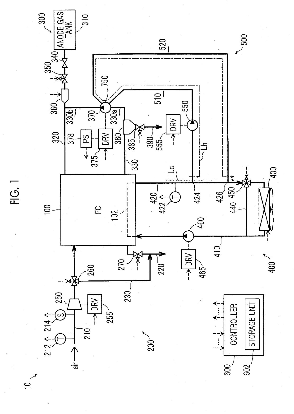
[0032]FIG. 1 is a diagram schematically showing a fuel cell system 10 according to a first embodiment. The fuel cell system 10 is mounted on, for example, a vehicle (fuel cell vehicle) and outputs electric power as a power source for a vehicle in response to a request from a driver. The fuel cell system 10 includes a fuel cell (FC) 100, a cathode gas supply portion 200, an anode gas supply portion 300, a FC cooling portion 400, a heating portion 500, and a controller 600.

[0033]The fuel cell 100 has a stack structure in which a plurality of single cells (not shown) as power generation units is stacked. In the embodiment, the fuel cell 100 is a solid polymer electrolyte fuel cell, but another type of fuel cell may be used. As a support of an electrode catalyst of the fuel cell 100, a carbon material is used.

[0034]The anode gas supply portion 300 includes an anode gas tank 310, an anode gas supply pipe 320, an anode gas circulation pipe 330, a main stop valve 340, a ...

second embodiment

B. Second Embodiment

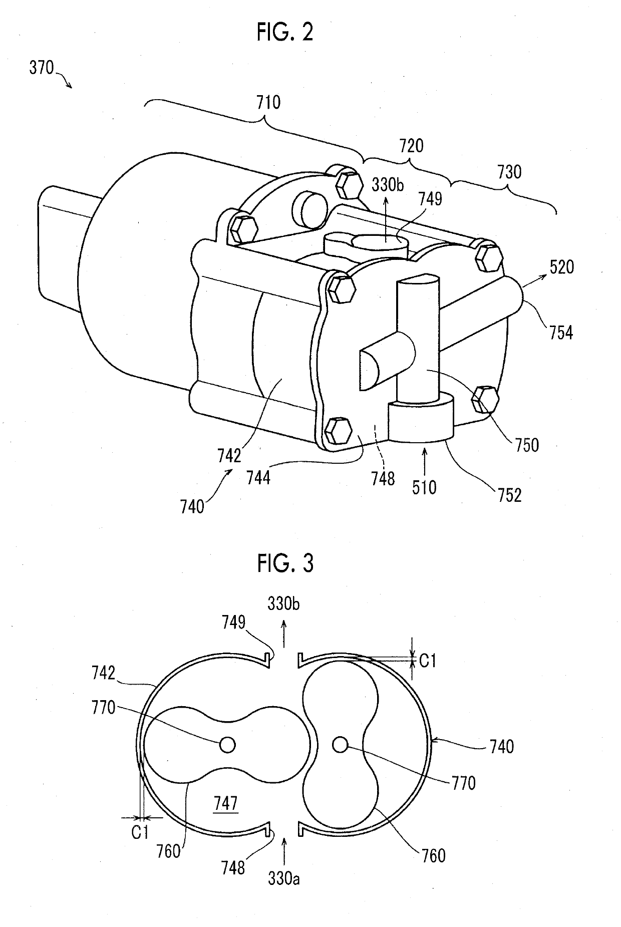
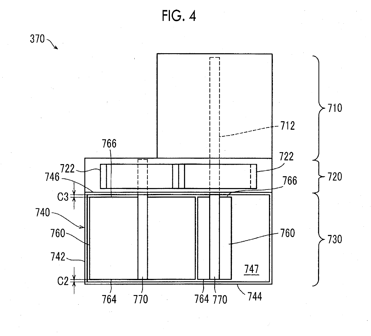
[0082]FIG. 7 is a diagram schematically showing a fuel cell system 10B according to a second embodiment. The fuel cell system 10B is different from the fuel cell system 10 according to the first embodiment in that: an environment temperature sensor 379 that detects an environment temperature of the anode gas pump 370 as the temperature corresponding to the temperature of the cylinder 740 of the anode gas pump 370 is provided; and a method of determining whether or not the pump temperature difference ΔTp is likely to be higher than or equal to the allowable temperature difference Tcr in the heating treatment of the controller 600 is different as described below. Other configurations of the fuel cell system 10B are the same as those of the fuel cell system 10 (FIG. 1) according to the first embodiment.

[0083]In the second embodiment, unlike the first embodiment, instead of obtaining the increased temperature of the rotor 760 as the pump temperature difference ΔTp, t...

third embodiment

C. Third Embodiment

[0088]FIG. 9 is a diagram schematically showing a fuel cell system 10C according to a third embodiment. The fuel cell system 10C is different from the fuel cell system 10 according to the first embodiment in that: an anode gas supply portion 300C is provided instead of the anode gas supply portion 300 of the fuel cell system 10 (FIG. 1) according to the first embodiment; and a method of determining whether or not the pump temperature difference ΔTp is higher than or equal to the allowable temperature difference Tcr in the heating treatment of the controller 600 is different as described below. Other configurations of the fuel cell system 10C are the same as those of the fuel cell system 10.

[0089]In the anode gas supply portion 300C, a gas temperature sensor 371 that detects a temperature of anode gas flowing into the anode gas pump 370, a flow rate sensor 372 that detects an inflow rate of the anode gas, and an inflow gas pressure sensor 373 that detects a pressur...


PUM

PropertyMeasurementUnit
temperatureaaaaaaaaaa

Abstract

The fuel cell system includes a fuel cell, a hydrogen circulation pump, heating portion, and a controller. The hydrogen circulation pump is configured to circulate hydrogen to the fuel cell and includes a cylinder and a rotor accommodated in the cylinder. The heating portion is configured to heat the cylinder. The controller is configured to control an operation of the heating portion. The controller is configured to cause the heating portion to heat the cylinder in a case where a driving state of the hydrogen circulation pump is higher than or equal to a standard driving state.

Description

INCORPORATION BY REFERENCE[0001]The disclosure of Japanese Patent Application No. 2017-220614 filed on Nov. 16, 2017 including the specification, drawings and abstract is incorporated herein by reference in its entirety.BACKGROUND1. Technical Field[0002]The present disclosure relates to a fuel cell system.2. Description of Related Art[0003]In a fuel cell system, typically, a hydrogen pump for circulating hydrogen to a hydrogen circulation path of the fuel cell system is provided. As the hydrogen pump, Japanese Unexamined Patent Application Publication No. 2017-089539 (JP 2017-089539 A) discloses an example in which heating means is provided in a housing of a hydrogen pump in order to restrain the housing of the hydrogen pump and a rotor accommodated in the housing from adhering to each other due to freezing.SUMMARY[0004]For the hydrogen pump used in the fuel cell system, further improvement of circulation efficiency is desired. In order to improve the circulation efficiency of the h...

Claims


Application Information

Patent Timeline
Patent Type & Authority Applications(United States)
IPC IPC(8): H01M8/04701H01M8/04007H01M8/0432H01M8/0438H01M8/04082
CPCH01M8/04738H01M8/04074H01M8/04373H01M8/04388H01M8/04328H01M8/04201H01M8/04029H01M8/04097H01M8/04425H01M8/04626H01M2008/1095H01M2250/20Y02E60/50Y02T90/40
Inventor KOZUKA, TOMOYUKI
Owner TOYOTA JIDOSHA KK
Why Eureka
Try Eureka