
Modularized vaporizer

Pending Publication Date: 2019-05-16
LV LAB
View PDF6 Cites 21 Cited by
  • Summary
  • Abstract
  • Description
  • Claims
  • Application Information

AI Technical Summary

Benefits of technology

The present invention provides a modularized vaporizer with several technical effects. Firstly, it avoids the generation of carbide by uniformly emitting heating energy towards a particular surface of fuel, while avoiding direct contact surfaces among a heating energy supply member, an absorbent member, and the fuel. Secondly, it converts fuel into a quantified solid type fuel to prevent excessive amount of a particular component being mixed and improve safety and reliability of the product. Thirdly, it allows for easy and convenient replacement of heating modules and absorbent members, and facilitates filling of fuel and replacing of absorbent members. Overall, the technical effects of the present invention are improved efficiency, safety, reliability, and convenience in vaporizing devices.

Problems solved by technology

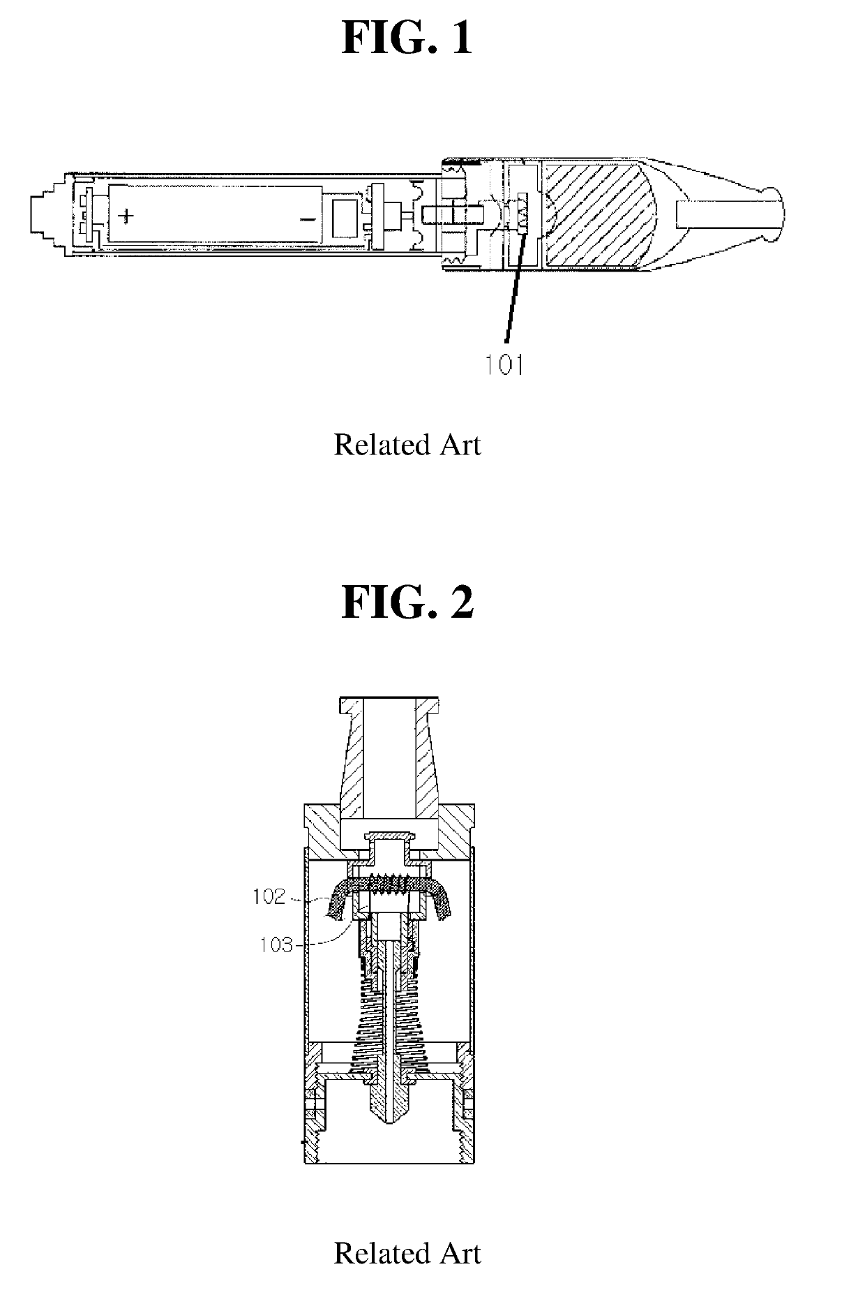
However, the above-described related art has problems that a carbide (harmful substance) is generated due to a direct contact part between a heating wire and an absorbent member or a part of a heating wire at a high temperature which does not come into surface-contact with a liquid but is exposed to the air, a risk is caused by an excessive amount of a particular component (particularly, an accident caused by an excessive amount of nicotine) being mixed when a liquid fuel is used, filling of fuel is inconvenient, a heating wire is wound on an absorbent member to transfer fuel to the heating wire to vaporize the fuel, and fuel is necessarily limited to a liquid type fuel.

Method used


Image

  • Modularized vaporizer
  • Modularized vaporizer
  • Modularized vaporizer

Examples


first exemplary embodiment

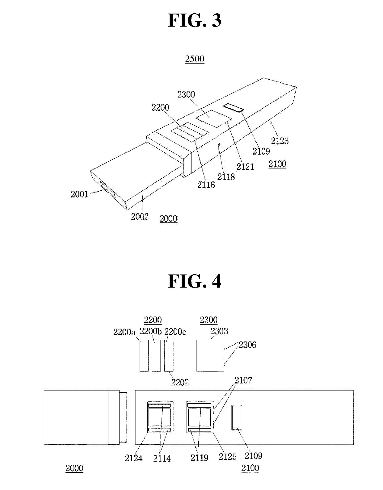
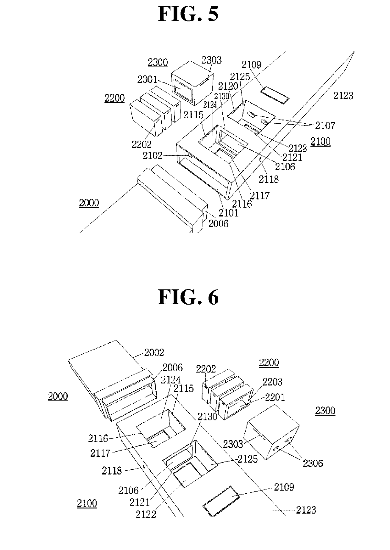
[0058]A modularized vaporizer 2500 according to a first exemplary embodiment of the present invention will be described with reference to FIGS. 3 and 4. An overall shape thereof may be a quadrangular shape as shown in FIG. 3 and may include a combination of a suction portion 2000 and a body portion 2100. The suction portion 2000 may include a suction aperture 2001 that passes through an inside of a suction body 2002 to discharge a vaporized fuel.

[0059]The body portion 2100 may include a fuel module chamber 2124, a heating module chamber 2125, and a button 2109. An air current aperture 2118, through which outside air flows into a vaporization space 2106, may be formed in one part of a side surface of a housing 2123.

[0060]In addition, the fuel module chamber 2124 and the heating module chamber 2125 may be configured such that both sides of corresponding parts of the housing 2123 are open. One open surface of the housing 2123 may have a size such that a fuel module 2200 and a heating m...

second exemplary embodiment

[0081]Hereinafter, a modularized vaporizer using a liquid fuel will be described. First, FIG. 11 illustrates a part receiving heating energy of a liquid fuel module 2200d and a part through which a liquid is injected.

[0082]The liquid fuel module 2200d may have a hollow quadrangular shape within which a liquid fuel is stored. A circular coupling portion 2210 having a thread (e.g., spiral line) may be formed on one surface to make an absorbent member 2204 replaceable. A free space 2211 may be formed on an outer circumferential surface of the coupling portion 2210 to facilitate rotating the absorbent member member module 2216. An inlet 2206 may be formed in another surface to fill a liquid fuel, and an elastic member 2208 having a sealing (waterproof) function may be disposed on an edge of the inlet 2206.

[0083]Further, the absorbent member 2204 may be formed of a heat-resistant material (glass fiber, cotton, Korean traditional paper, natural lumber, natural stone, a heat-resistant carb...

third exemplary embodiment

[0087]In the present invention, coupling or separating a fuel module with or from a housing in a drawer manner may be performed by separating the suction portion 2000 from the body portion 2100 and inserting a fuel module 2200e into a fifth open surface 2129 of the fuel module chamber 2124 included in the body portion 2100.

[0088]In coupling and separating between the fuel module 2200e and the fuel module chamber 2124, like the first exemplary embodiment, the coupling structure may include a magnet, a structure of a concave line and a convex line, or the like. The fuel module 2200e is not limited to a solid or liquid fuel and may include a handle 2207 on one surface thereof to be coupled or separated more easily.


PUM


Abstract

The present invention relates to a modularized vaporizer, which enables a fuel module, a heating module, or a vaporizing module to be coupled and separated, in a drawer manner, to and from a body portion housing since a fuel module chamber, a heating module chamber, or a vaporizing module chamber is provided in the body portion housing. The modularized vaporizer reduces the carbonization of fuel or an absorbent member since the fuel or a surface of the absorbent member is uniformly heated (irradiation) by heating energy (light, beam, or heat) emitted (irradiation) from a heating member of the heating module.

Description

CROSS-REFERENCE TO RELATED APPLICATIONS[0001]This application is a Continuation in Part application of International Application No. PCT / KR2017 / 007570 filed on Jul. 14, 2017, which claims priority to Korean Patent Application No. KR 10-2016-0090339 filed on Jul. 16, 2016, which applications are incorporated herein by reference.TECHNICAL FIELD[0002]The present invention relates to a device that vaporizes fuel, and more particularly, to a vaporizer applied to an antismoking adjuvant, an electronic cigarette, a fumigation treatment device, and the like which vaporize a liquid (fuel) using a vaporization device using electrical energy generated by a battery.RELATED ART[0003]Vaporizers such as an antismoking adjuvant, an electronic cigarette, a fumigation treatment device, and the like have been developed and used for helping people with quitting smoking.[0004]Such devices generally include a suction portion, a cartridge, and a battery portion. The cartridge includes a liquid accommodati...

Claims


Application Information

Patent Timeline
IPC IPC(8): A24F47/00A24B15/16F22B3/02A24F40/10A24F40/44A24F40/46A24F40/48A24F40/485A24F40/50
CPCA24F47/008A24B15/167F22B3/02A61M15/06A61M11/041A61M2205/368A61M15/0003A61M2205/8206A24F40/46A24F40/10A24F40/44A24F40/48A24F40/50A24F40/485A61M11/042A61M2205/3673A24F40/42A24F40/95A24D1/14A61M2205/123
Inventor SEOK, INSUN
Owner LV LAB
Learn More