
Engineering change order (ECO) cell architecture and implementation

a cell and engineering change technology, applied in the field of engineering change order (eco) designs, can solve the problems of increasing the number of masks required in the manufacturing process, complex multi-mask process, and high cost of multi-mask processes

Inactive Publication Date: 2019-05-09
QUALCOMM INC
View PDF0 Cites 16 Cited by
  • Summary
  • Abstract
  • Description
  • Claims
  • Application Information

AI Technical Summary

Benefits of technology

The patent describes a new cell structure that allows for easy modification and repurposing without requiring extensive mask changes. This cell structure can be used as a filler cell or a decoupling capacitor cell, and can also be customized as needed. The cell structure includes power rails and vias that allow for convenient power delivery and easy repurposing. The technical effects of this patent include reducing costs and time delays during mask redesigns.

Problems solved by technology

The use of such multi-pattern mask processes further increases the number of masks required in the manufacturing process.
Because most of the multi-patterned layers are used early in the manufacturing process, most of the complexity in the manufacturing process is associated with the front-end-of-line (FEOL) transistor formation and middle-end-of-line (MEOL or MOL) local interconnect and lower levels of metal formation.
It should be appreciated that such complex, multi-mask processes are expensive.
Consequently, if a design defect is detected, there is a substantial expense in redesigning the masks and a substantial delay in resuming manufacturing.
However, the viability of such use is dependent on the composition and location of the filler cell(s) relative to the logic error.
Then, if a design defect is detected, the changes can be made beginning at the level incorporating the ECO instead of starting from the beginning with all FEOL, MEOL, and many of the BEOL masks being regenerated with accompanying expense and delay.
However, while such filler cells may be configured to create needed simple logic functions, the filler cells may still need many FEOL masks to be redefined.

Method used


Image

  • Engineering change order (ECO) cell architecture and implementation
  • Engineering change order (ECO) cell architecture and implementation
  • Engineering change order (ECO) cell architecture and implementation

Examples


Embodiment Construction

[0050]With reference now to the drawing figures, several exemplary aspects of the present disclosure are described. The word “exemplary” is used herein to mean “serving as an example, instance, or illustration.” Any aspect described herein as “exemplary” is not necessarily to be construed as preferred or advantageous over other aspects,

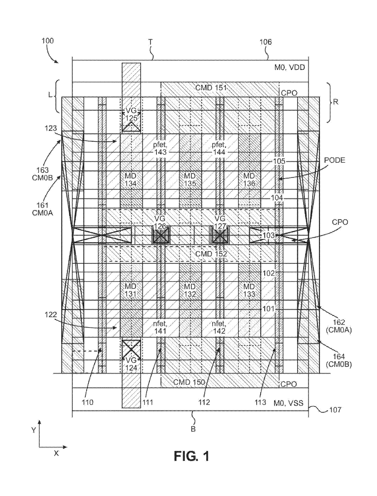
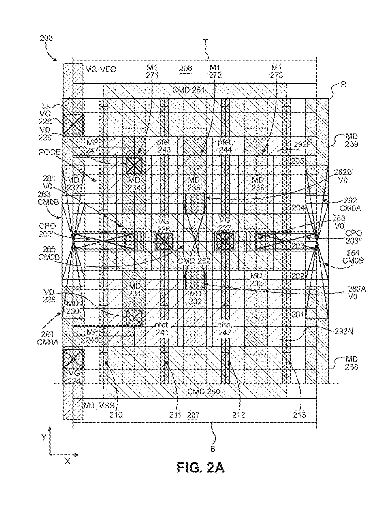
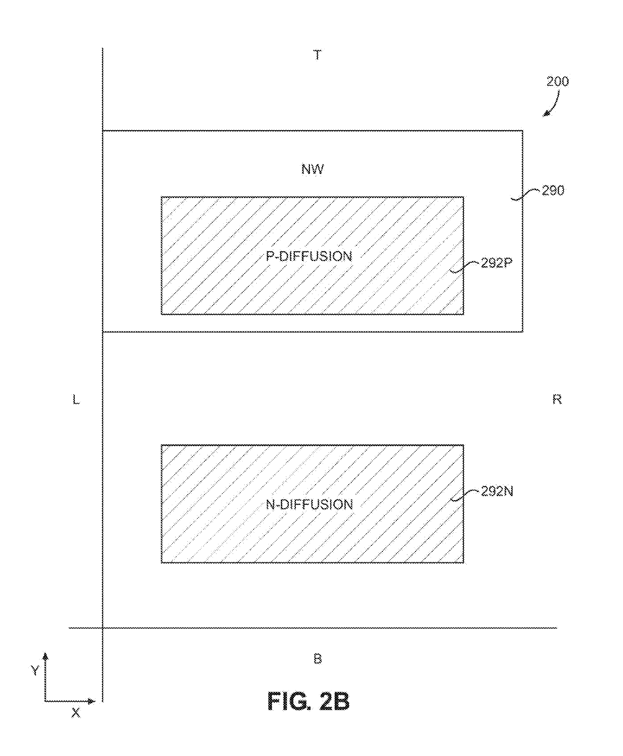
[0051]Aspects disclosed in the detailed description include engineering change order (ECO) cell architecture and implementation. In particular, exemplary aspects disclosed herein provide a generic cell structure that may be readily modified to effect an ECO without requiring extensive mask changes beyond one or two levels including the level in which the cell is located. Further, this generic cell structure can be “parked” fairly deep in the manufacturing process, such as in the middle-end-of-line (MEOL), so that fewer changes to other masks are needed in the event of a change. The generic cell may further act as a filler cell for pattern density. Inc...


PUM

PropertyMeasurementUnit
sizesaaaaaaaaaa
sizeaaaaaaaaaa
timeaaaaaaaaaa

Abstract

Engineering change order (ECO) cell architecture and implementation is disclosed. In particular, exemplary aspects disclosed herein provide a generic cell structure that may be readily modified to effect an ECO without requiring extensive mask changes beyond one or two levels including the level in which the cell is located. Further, this generic cell structure can be “parked” fairly deep in the manufacturing process, such as in the middle-end-of-line (MEOL), so that fewer changes to other masks are needed in the event of a change. The generic cell may further act as a filler cell for pattern density. Inclusion of such a generic cell in a circuit design can help alleviate the need for extensive mask redesign and accompanying delays in the production of finished silicon.

Description

PRIORITY CLAIM[0001]The present application claims priority under 35 U.S.C. § 119(e) to U.S. Provisional Patent Application Ser. No. 62 / 582,406, filed on Nov. 7, 2017 and entitled “ENGINEERING CHANGE ORDER (ECO) CELL ARCHITECTURE AND IMPLEMENTATION,” the contents of which is incorporated herein by reference in its entirety.BACKGROUNDField of the Disclosure[0002]The technology of the disclosure relates generally to improving engineering change order (ECO) designs in the manufacture of integrated circuits (ICs).II. Background[0003]Computing devices have become increasingly common in modern society. Early computers were the size of a room and employed vacuum tubes to provide rudimentary mathematical calculations. In contrast, modern computing devices provide myriad multimedia, telephony, word processing, and other functions in a relatively small package relying on integrated circuits (ICs). The industry feels market pressure to provide ever increasing processing options in increasingly...

Claims


Application Information

Patent Timeline
Patent Type & Authority Applications(United States)
IPC IPC(8): G06F17/50G03F1/70
CPCG06F17/5077G03F1/70G06F17/5022H01L27/0207G06F2117/06G06F2119/18G06F30/392G06F30/39Y02P90/02G06F30/394G06F30/33G06F30/398
Inventor CORREALE, JR., ANTHONYGOODALL, III, WILLIAM
Owner QUALCOMM INC
Learn More