
Method of obtaining measurements, apparatus for performing a process step, and metrology apparatus

a technology of measurement and process step, applied in the direction of photomechanical equipment, semiconductor/solid-state device testing/measurement, instruments, etc., can solve the problems of overlay error, time available per wafer not allowing measurement of all alignment marks, and the error of placing product features, etc., to improve the relevance of measurement results

Active Publication Date: 2019-05-09
ASML NETHERLANDS BV
View PDF1 Cites 9 Cited by
  • Summary
  • Abstract
  • Description
  • Claims
  • Application Information

AI Technical Summary

Benefits of technology

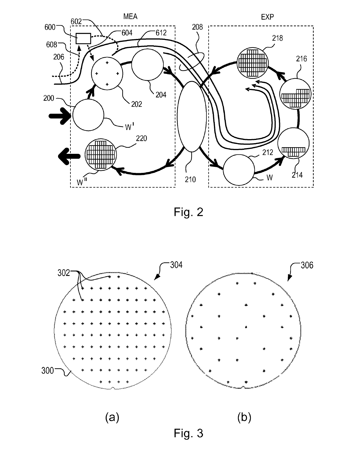
The present invention aims to improve the relevance of measurement results without necessarily increasing the number of measurement locations required to be measured. It involves dynamic selection of the set of measurement locations based on their relevance for performance improvement, without increasing the total number of measurements and measurement time. This can reduce the performance penalty that might otherwise be expected to result from choosing a limited set of measurement locations. The supplementary data can comprise statistical data based on previously processed substrates and the weighting factor can be used to reduce the influence of outlier measurements on future processing.

Problems solved by technology

A key performance parameter of the lithographic process is the overlay error.
This error, often referred to simply as “overlay”, is the error in placing product features in the correct position relative to features formed in previous layers.
However, the time available per wafer does not permit measurement of all the alignment marks, and a compromise between speed and accuracy inevitably has to be made.
Some of these errors may be uncorrectable noise, for example, but others are correctable using available techniques in theory, but not economically correctable in practice.
Again, even if there is a high spatial density of possible measurement locations, to actually measure such a number of measurement locations would adversely affect throughput of the lithographic process of the metrology apparatus.
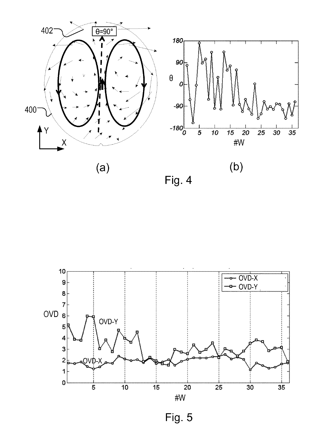
A problem arises, however, in that the process fingerprints can vary quite widely even with a single lot of wafers.
The set of measurement locations that gives good overlay performance for one wafer may not give good overlay performance for the next one.
Another problem that affects both alignment and metrology performance is that of anomalous samples or “outliers”.
When this measurement is included in the alignment model, however, the influence of the anomalous measurement may spread, degrading overlay performance over and unduly wide area.
Similarly, outliers in performance metrology may cause noise and degradation in advanced performance control loops.

Method used


Image

  • Method of obtaining measurements, apparatus for performing a process step, and metrology apparatus
  • Method of obtaining measurements, apparatus for performing a process step, and metrology apparatus
  • Method of obtaining measurements, apparatus for performing a process step, and metrology apparatus

Examples


Embodiment Construction

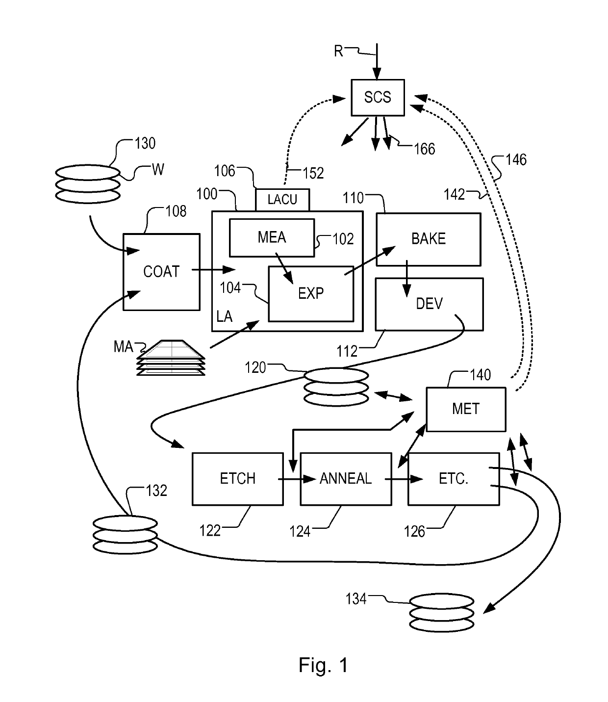
[0045]Before describing embodiments of the invention in detail, it is instructive to present an example environment in which embodiments of the present invention may be implemented.

[0046]FIG. 1 at 100 shows a lithographic apparatus LA as part of an industrial facility implementing a high-volume, lithographic manufacturing process. In the present example, the manufacturing process is adapted for the manufacture of for semiconductor products (integrated circuits) on substrates such as semiconductor wafers. The skilled person will appreciate that a wide variety of products can be manufactured by processing different types of substrates in variants of this process. The production of semiconductor products is used purely as an example which has great commercial significance today.

[0047]Within the lithographic apparatus (or “litho tool”100 for short), a measurement station MEA is shown at 102 and an exposure station EXP is shown at 104. A control unit LACU is shown at 106. In this example...


PUM

PropertyMeasurementUnit
heightaaaaaaaaaa
structuresaaaaaaaaaa
thermal deformationaaaaaaaaaa

Abstract

Measurements are obtained from locations across a substrate before or after performing a lithographic process step. Examples of such measurements include alignment measurements made prior to applying a pattern to the substrate, and measurements of a performance parameter such as overlay, after a pattern has been applied. A set of measurement locations is selected from among all possible measurement locations. At least a subset of the selected measurement locations are selected dynamically, in response to measurements obtained using a preliminary selection of measurement locations. Preliminary measurements of height can be used to select measurement locations for alignment. In another aspect, outlier measurements are detected based on supplementary data such as height measurements or historic data.

Description

CROSS-REFERENCE TO RELATED APPLICATIONS[0001]This application claims priority of EP application EP16169384 which was filed on May 12, 2016, EP application EP16188380 which was filed on Sep. 12, 2016 and EP application EP17163586 which was filed on Mar. 29, 2017 which are incorporated herein in its entirety by reference.BACKGROUNDField of the Invention[0002]The present invention relates to methods of obtaining measurements from locations across one or more substrates. The invention can be applied for example in a lithographic apparatus, or in a metrology apparatus. The present invention further relates to methods of manufacturing devices using such lithographic apparatus, and to data processing apparatuses and computer program products for implementing parts of such a method.Background Art[0003]A lithographic apparatus is a machine that applies a desired pattern onto a substrate, usually onto a target portion of the substrate. A lithographic apparatus can be used, for example, in the...

Claims


Application Information

Patent Timeline
Patent Type & Authority Applications(United States)
IPC IPC(8): G03F7/20G03F9/00G01N21/956H01L21/66
CPCG03F7/70633G03F9/7046G01N21/956H01L22/12H01L22/20G03F7/70625
Inventor CEKLI, HAKKI ERGUNISHIBASHI, MASASHIVAN DE VEN, WENDY JOHANNA MARTHINAROELOFS, WILLEM SEINE CHRISTIANMC NAMARA, ELLIOTT GERARDRAHMAN, RIZVIKUPERS, MICHIELSCHMITT-WEAVER, EMIL PETERDELVIGNE, ERILK HENRI ADRIAAN
Owner ASML NETHERLANDS BV
Learn More