
Method and apparatus for repurposing well sites for geothermal energy production

Inactive Publication Date: 2019-05-02
EAVOR TECH INC
View PDF3 Cites 22 Cited by
  • Summary
  • Abstract
  • Description
  • Claims
  • Application Information

AI Technical Summary

Benefits of technology

The present invention is about improving the efficiency and economics of unused wells. This is done by using waste heat from the well as a preheat treatment for the feed stream that is reinjected into the system. This technology helps reduce power generation apparatus costs and also contributes to a reduction in capital expenditures. Additionally, this technology helps mitigate well abandonment costs for the government and oil industry and minimizes the environmental impact due to the subterranean placement of the horizontal segments of the wells.

Problems solved by technology

From an environmental point of view, this requires invasive operations which ultimately affect the landscape of an area scheduled for geothermal development.
As such, this amount of energy is too substantive too leave unused.
Although useful in certain scenarios, the limitation with this arrangement relates to the confined interior volume of the drill string and further only a small area of the loop is exposed to a geothermal zone.
This inherently limits efficient heat transfer.
This does nothing to control improperly maintained unused wells and in fact may contribute to new problems.
This over simplification does not address the fact that several new wells are required which adds cost and provides no instruction regarding the connection or thermal management of the multiple feed streams.
The publication expresses a concern about geo-fluid loss and thus temperature loss and does not provide any teachings to mitigate the east-west problems associated with directional drilling, i.e. magnetic interference, fish, heavy iron concentration in the formation inter alia.

Method used


Image

  • Method and apparatus for repurposing well sites for geothermal energy production
  • Method and apparatus for repurposing well sites for geothermal energy production
  • Method and apparatus for repurposing well sites for geothermal energy production

Examples


Embodiment Construction

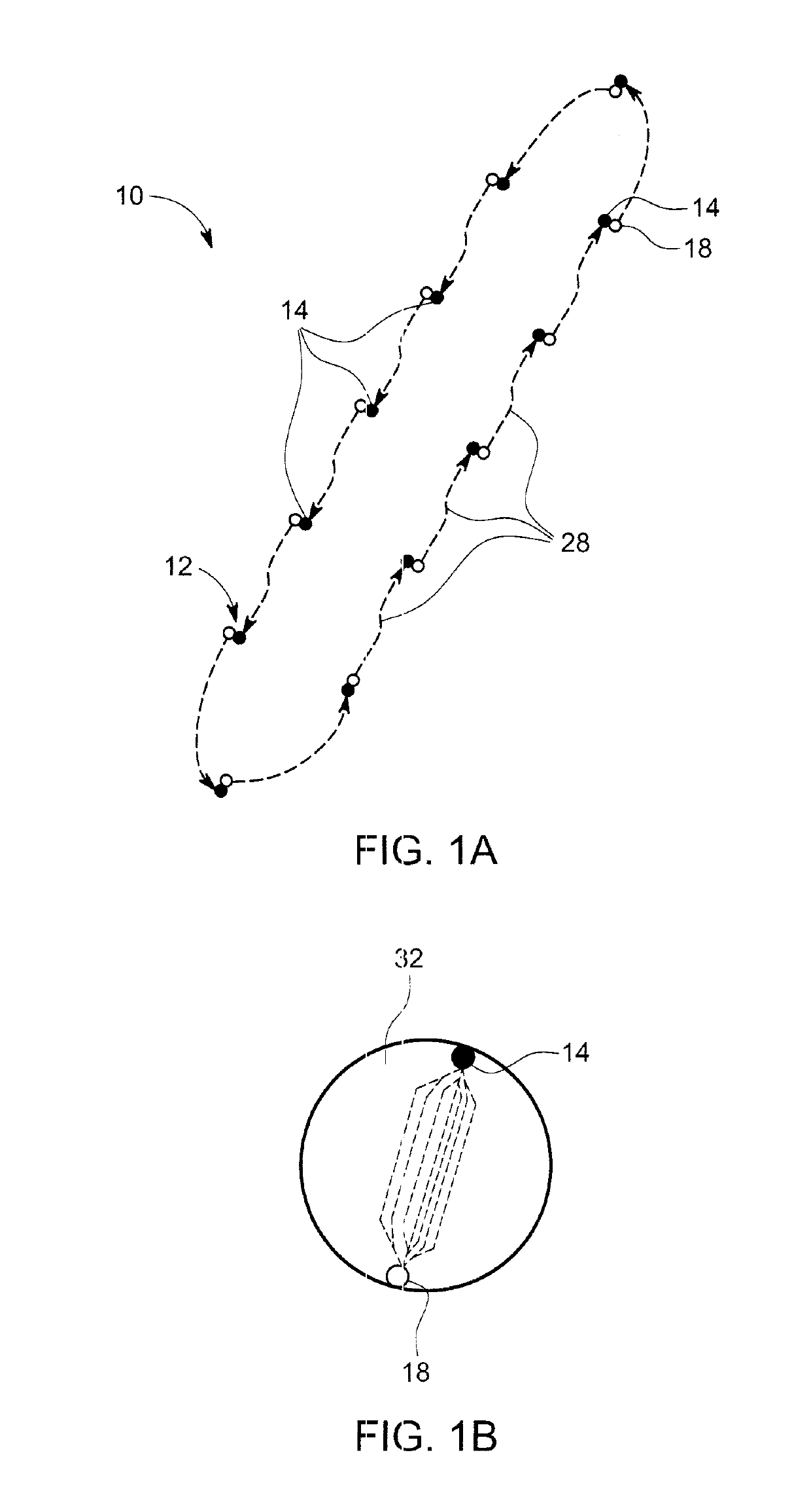
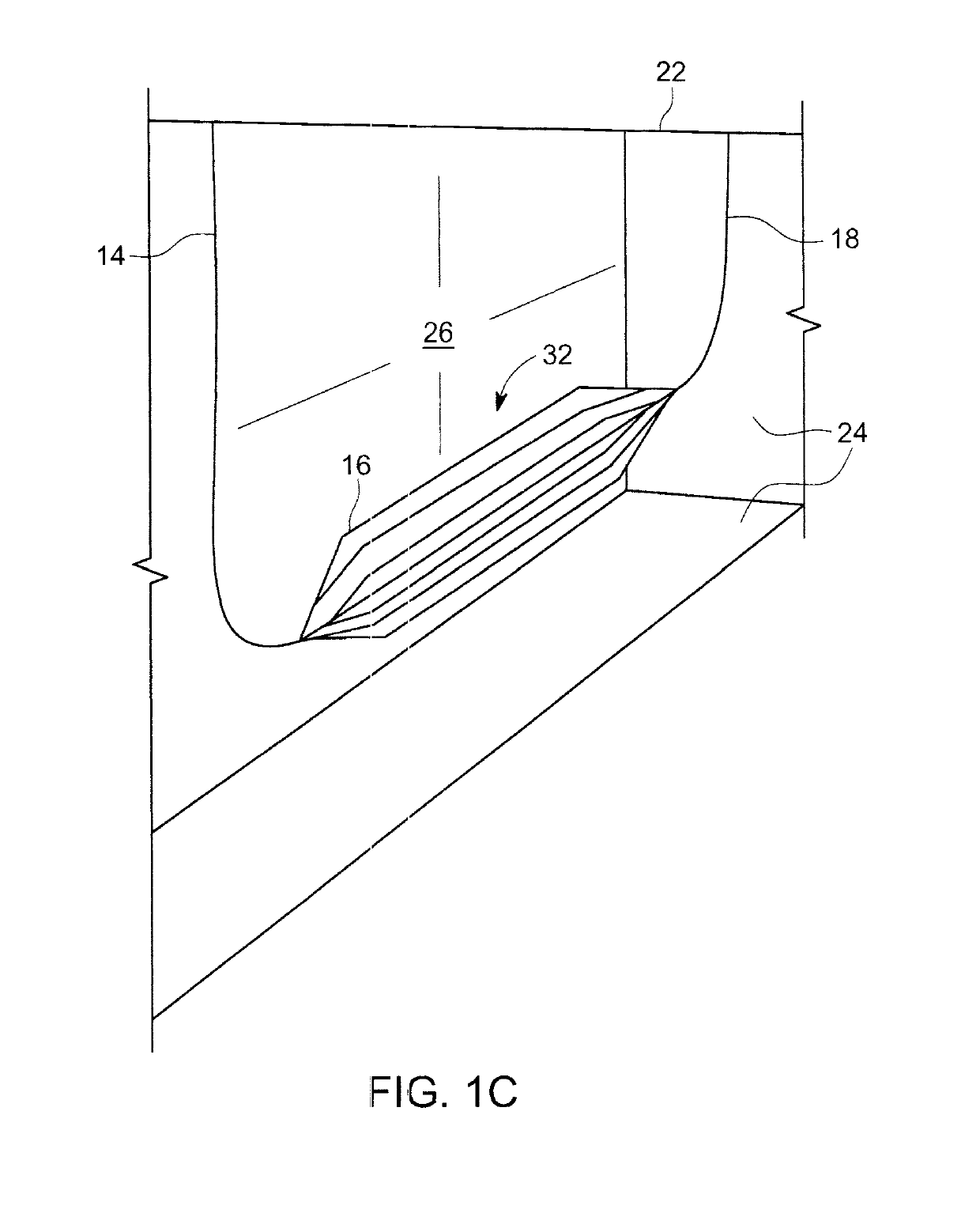
[0045]Referring now collectively to FIGS. 1, 1A and B shown is a schematic illustration of a daisy chain of wells, globally denoted by numeral 10. In this embodiment, each surface location, generally denoted by numeral 12, includes an injection well 14 connected to a lateral well conduit 16 and production well 18. In this manner, the continuous well structure subscribes to a generally U shaped structure, best referenced in FIG. 1B.

[0046]As illustrated in FIG. 1, each location 12 is discrete and linked to proximal locations in an elegant and advantageous manner. As an example, the distance between locations may be 3,500 meters. This will, of course, vary from one situation to another. Reference to FIG. 1B delineates linkage specification.

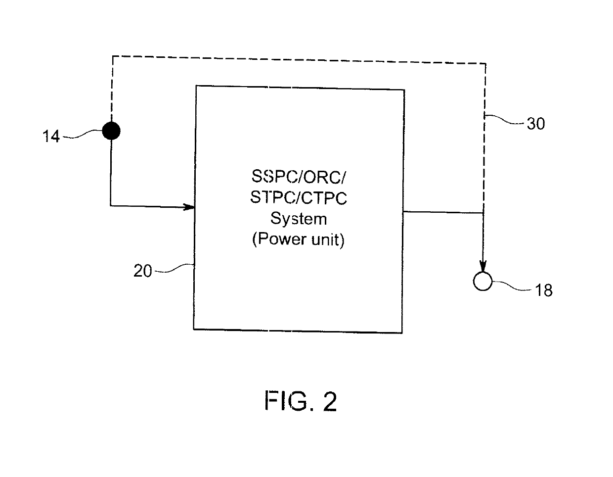
[0047]In FIG. 2, numeral 20 is representative of the power generation apparatus. Selections for the apparatus 20 will be discussed herein after, however for purposes of discussion, the apparatus 20 is responsible for converting steam into electrical ...


PUM


Abstract

A method and system for capturing geothermal energy. Injection and production well pairs in a geothermal zone are connected with a power generation apparatus between the production well of one well pair and the injection well of an adjacent well pair in a subterranean closed loop daisy chain configuration. Fluid circulated through the loop and the power generation apparatus recover subterranean heat energy. Specification is also disclosed in respect of application of the technology to repurpose an unused or suspended oilfield.

Description

[0001]The present invention relates to a method and apparatus for repurposing well sites in an economical and environmentally responsible manner.BACKGROUND OF THE INVENTION[0002]The benefits of geothermal energy are well known and have been the subject matter of many publications and patents. The general concept is to drill into a formation to extract heat therefrom and return the generated steam and water to the surface where the steam drives, for example, a power generating device. From an environmental point of view, this requires invasive operations which ultimately affect the landscape of an area scheduled for geothermal development.[0003]Existing well sites have some commonality with geothermal sites, but offer preexistence in the landscape, a processed tract of land and wells. There are are a plethora of unused or suspended wells in Alberta which remain as such in view of the cleanup cost. It has been proposed, without effect or implementation, to capture geothermal heat from...

Claims


Application Information

Patent Timeline
IPC IPC(8): F24T10/15
CPCF24T10/15F24T2010/53F03G7/04F24T10/20F24T10/10Y02E10/46Y02E10/10
Inventor REDFERN, JOHN
Owner EAVOR TECH INC
Learn More