
Residue Handling System for an Agricultural Harvester

Active Publication Date: 2019-05-02
BLUE LEAF I P
View PDF28 Cites 10 Cited by
  • Summary
  • Abstract
  • Description
  • Claims
  • Application Information

AI Technical Summary

Benefits of technology

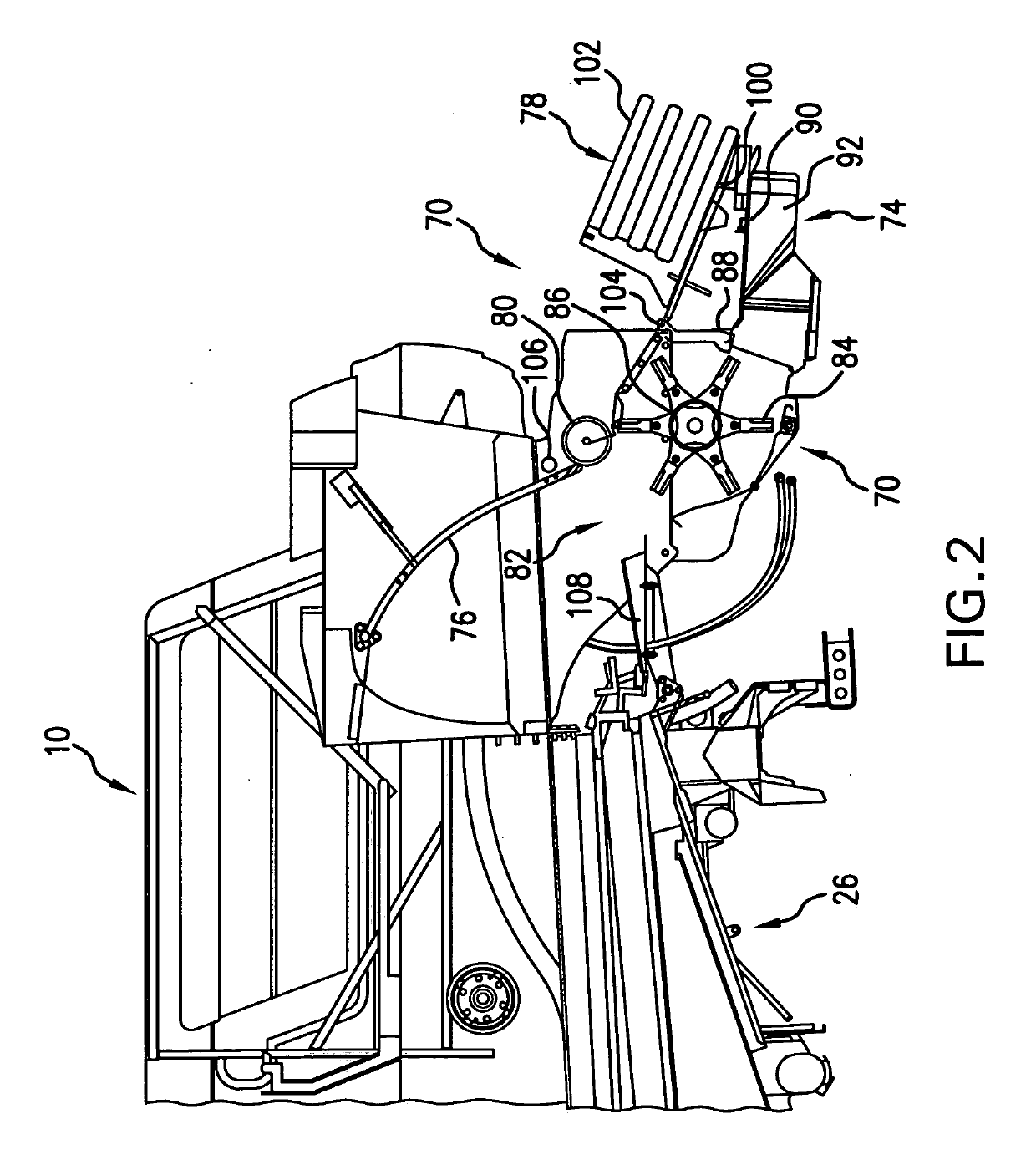
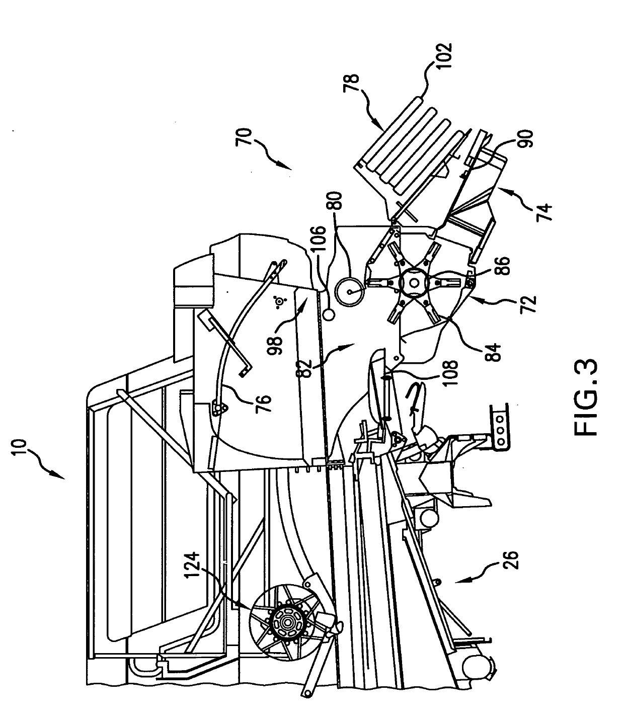
The present invention is a residue handling system for a harvester that has several advantages. It is lightweight and can be easily switched between different modes of operation. The feed roller can be reversed and can be moved between different operating positions or a second feed roller can be used. The operating angular orientation of the swath board can be varied depending on the position of the door. The mechanical drive occupies minimum space onboard the harvester and does not interfere with the placement or operation of other components. An infeed pan can be used in front of the chopper and folded between feed and bypass positions.

Problems solved by technology

However, with some configurations of residue choppers, not all material enters the chopper to be processed.
Further, choppers that may capture all of the material discharged from the machine do not permit a convenient drive line path due to other components on the vehicle that may not be readily moved, such as fuel tanks, diesel exhaust fluid (DEF) tanks, etc.
Further, existing systems do not provide a convenient method of converting between various residue handling modes and may provide poor performance due to the disruption of the flow of straw when the system is in a particular mode.
Additionally, such choppers typically do not have a configuration that permits the chaff and weed seeds from the cleaning shoe to be windrowed behind the machine and not spread out, while simultaneously chopping and spreading the straw.

Method used


Image

  • Residue Handling System for an Agricultural Harvester
  • Residue Handling System for an Agricultural Harvester
  • Residue Handling System for an Agricultural Harvester

Examples


Embodiment Construction

[0034]The terms “grain”, “straw” and “tailings” are used principally throughout this specification for convenience but it is to be understood that these terms are not intended to be limiting. Thus “grain” refers to that part of the crop material which is threshed and separated from the discardable part of the crop material, which is referred to as non-grain crop material, MOG or straw. Incompletely threshed crop material is referred to as “tailings”. Also the terms “forward”, “rearward”, “left” and “right”, when used in connection with the agricultural harvester and / or components thereof are usually determined with reference to the direction of forward operative travel of the harvester, but again, they should not be construed as limiting. The terms “longitudinal” and “transverse” are determined with reference to the fore-and-aft direction of the agricultural harvester and are equally not to be construed as limiting.

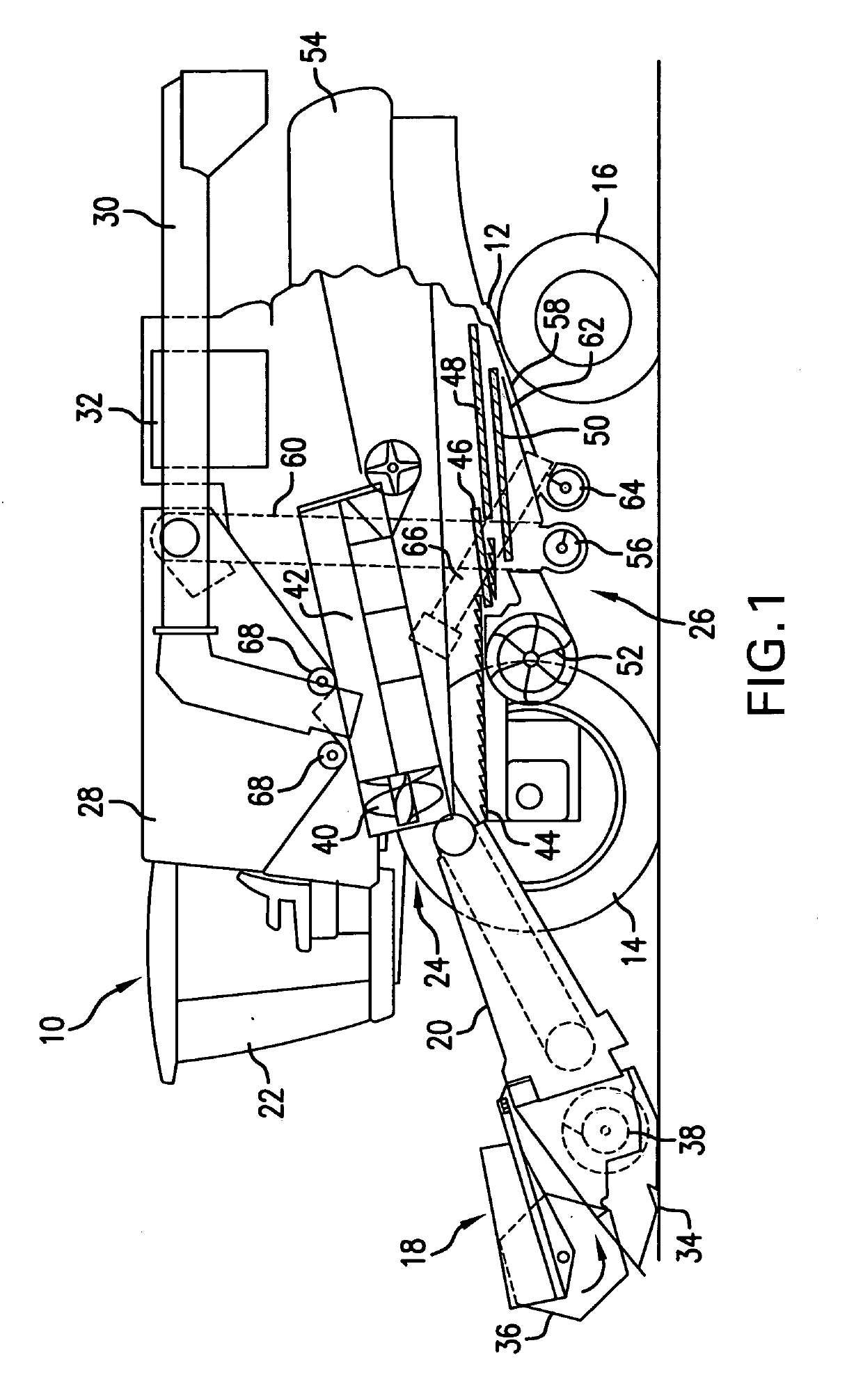
[0035]Referring now to the drawings, and more particularly to FIG. 1...


PUM


Abstract

An agricultural harvester includes a threshing and separating system for separating grain from non-grain crop material, and a residue handling system for receiving at least a portion of the non-grain crop material. The residue handling system includes a chopper and a windrow arrangement, each having an inlet. A door is movable between a closed position which directs the non-grain crop material to the chopper and an open position which directs the non-grain crop material to the windrow arrangement. A feed roller is positioned adjacent to and between the inlet of the chopper and windrow arrangement. The feed roller is rotatable in a first direction which directs the non-grain crop material to the chopper when the door is in the closed position, and a second direction which directs the non-grain crop material to the windrow arrangement when the door is in the open position.

Description

BACKGROUND OF THE INVENTION1. Field of the Invention[0001]The present invention relates to agricultural harvesters such as combines, and, more particularly, to residue spreader systems used with such harvesters.2. Description of the Related Art[0002]An agricultural harvester known as a “combine” is historically termed such because it combines multiple harvesting functions with a single harvesting unit, such as picking, threshing, separating and cleaning. A combine includes a header which removes the crop from a field, and a feeder housing which transports the crop matter into a threshing rotor. The threshing rotor rotates within a perforated housing, which may be in the form of adjustable concaves, and performs a threshing operation on the crop to remove the grain. Once the grain is threshed it falls through perforations in the concaves onto a grain pan. From the grain pan the grain is cleaned using a cleaning system, and is then transported to a grain tank onboard the combine. The ...

Claims


Application Information

Patent Timeline
IPC IPC(8): A01F12/46A01F12/44A01F12/40A01F17/02A01F29/04A01D41/12
CPCA01F12/46A01F12/444A01D41/1243A01F17/02A01F29/04A01F12/40
Inventor FARLEY, HERBERT M.ISAAC, NATHAN E.BIRKEL, ANDREWJACKSON, AUSTIN L.
Owner BLUE LEAF I P
Learn More