
Switchable luminance LED light bulb

Active Publication Date: 2013-12-12
RGT UNIV OF CALIFORNIA
View PDF2 Cites 14 Cited by
  • Summary
  • Abstract
  • Description
  • Claims
  • Application Information

AI Technical Summary

Benefits of technology

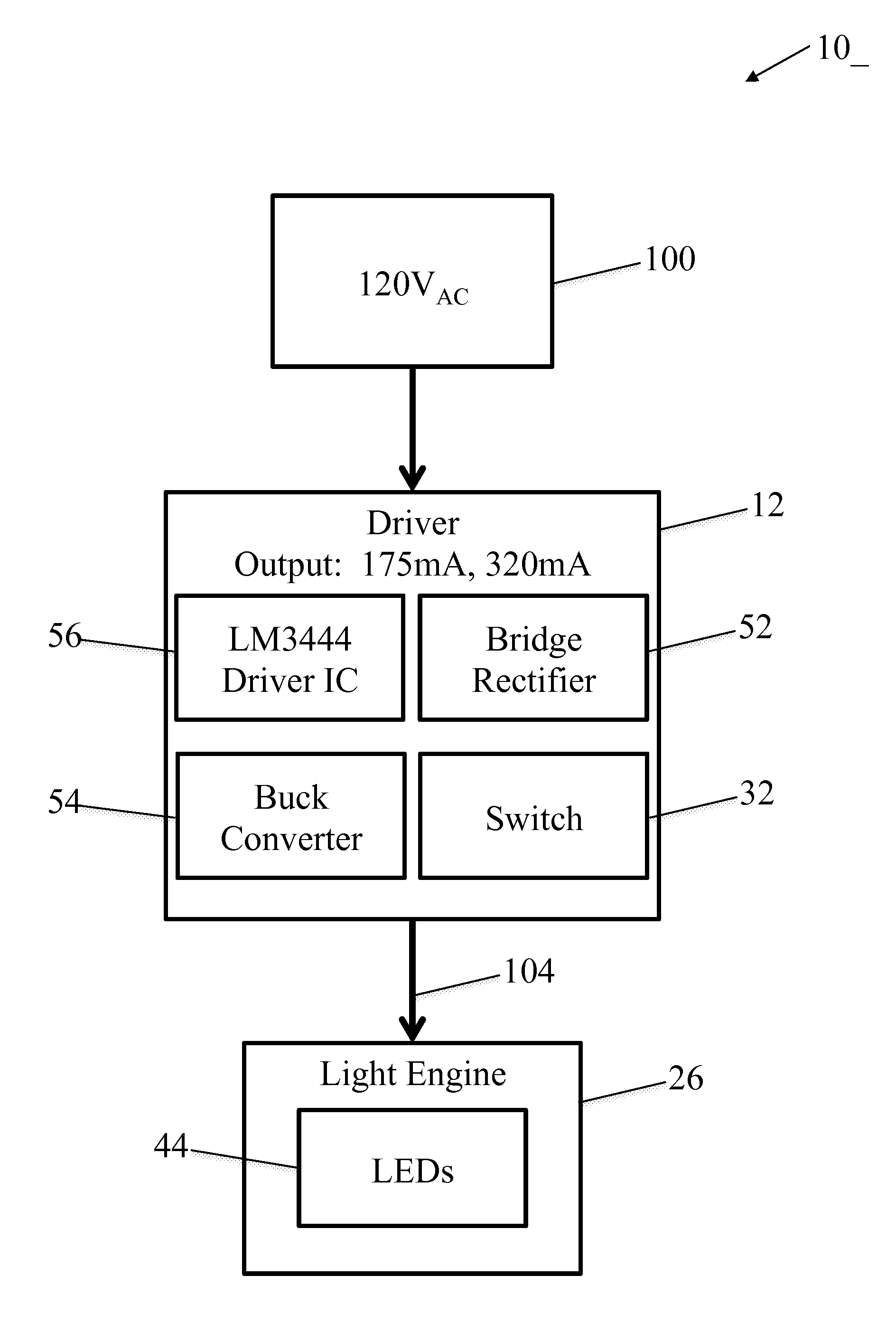
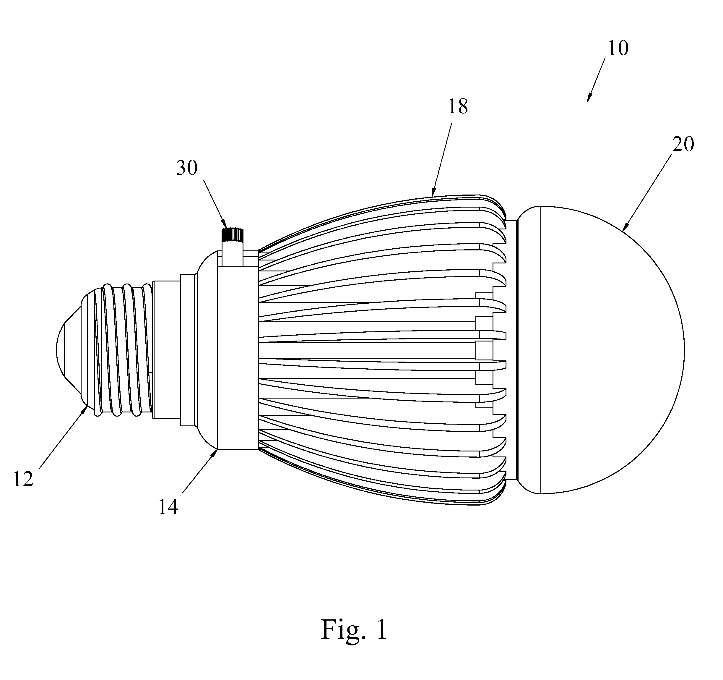
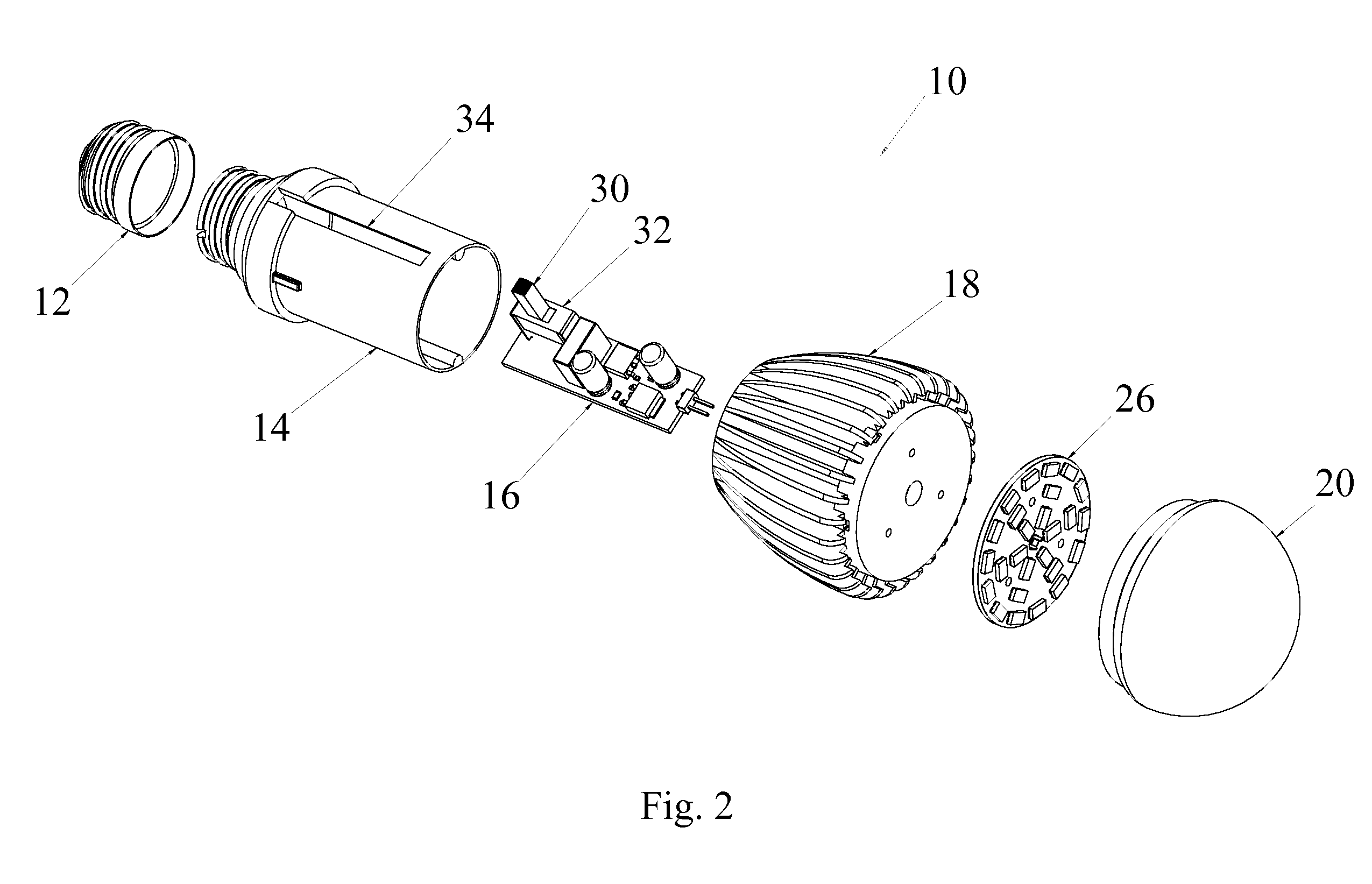
This patent is about a switch that can be adjusted to different positions, each associated with a different brightness of the LEDs. The switch can be turned on or off to control the flow of current and the intensity of the LEDs. This allows for a more complex and versatile LED light bulb that can switch between different levels of brightness. This technology is novel and has great commercial value.

Problems solved by technology

While white light LED light bulbs have proven to be highly successful they have lacked one feature available in traditional incandescent light bulbs: the ability to provide multiple light outputs from one lamp.

Method used


Image

  • Switchable luminance LED light bulb
  • Switchable luminance LED light bulb
  • Switchable luminance LED light bulb

Examples


Embodiment Construction

[0025]In the figures like numbers refer to like elements throughout. Additionally, the terms “a” and “an” as used herein do not denote a limitation of quantity, but rather denote the presence of at least one of the referenced items. All publications mentioned herein are incorporated by reference for all purposes to the extent allowable by law.

[0026]The presently disclosed subject matter now will be described more fully hereinafter with reference to the accompanying drawings in which a specific embodiment is shown. However, it should be understood that this invention may take many different forms and thus it should not be construed as being limited to the specific embodiments set forth herein.

[0027]The invention encompasses a light bulb comprised of a plurality of LEDs having switch controlled illumination intensities.

[0028]In a broad embodiment, the invention encompasses a light bulb device comprising an AC electrical input, a plurality of (one or more) LEDs capable of emitting vari...


PUM


Abstract

A switchable luminance LED light bulb, including embodiments that may be used with any common commercial fitting.

Description

RELATIONSHIP TO OTHER APPLICATIONS[0001]The present application claims priority to, and the benefit of the following applications that are entirely incorporated by reference to the fullest extent allowable by law: U.S. application Ser. No. 6,165,6021 filed 6 Jun. 2012 titled ‘Switchable LED Light Bulb’ and U.S. application Ser. No. 61,667,982 filed 4 Jul. 2012 titled ‘Switchable Luminance LED Light Bulb’.FIELD OF THE INVENTION[0002]The presently disclosed subject matter is directed towards LED-type light bulbs. More particularly the presently disclosed subject matter relates to LED-type light bulbs that have switch controlled illumination intensities.BACKGROUND OF THE INVENTION[0003]While white light LED light bulbs have proven to be highly successful they have lacked one feature available in traditional incandescent light bulbs: the ability to provide multiple light outputs from one lamp. For example, 3-way Edison light bulbs are widely used to provide switchable light outputs. A 3...

Claims


Application Information

Patent Timeline
IPC IPC(8): H05B33/08H05B44/00
CPCH05B33/0839Y02B20/30H05B45/345H05B45/30H05B45/10H05B45/375
Inventor MUNDAY, DAVID
Owner RGT UNIV OF CALIFORNIA
Learn More