
System for generating synthetic aperture ultrasound images during needle placement

a synthetic aperture and ultrasound technology, applied in the field of needle placement systems, can solve the problems of almost always blindly performing the procedure, the phenomenon of bending becomes a serious issue in obese and obstetric patients, and worse in obese and elderly patients

Active Publication Date: 2019-04-25
THE JOHN HOPKINS UNIV SCHOOL OF MEDICINE
View PDF0 Cites 8 Cited by
  • Summary
  • Abstract
  • Description
  • Claims
  • Application Information

AI Technical Summary

Benefits of technology

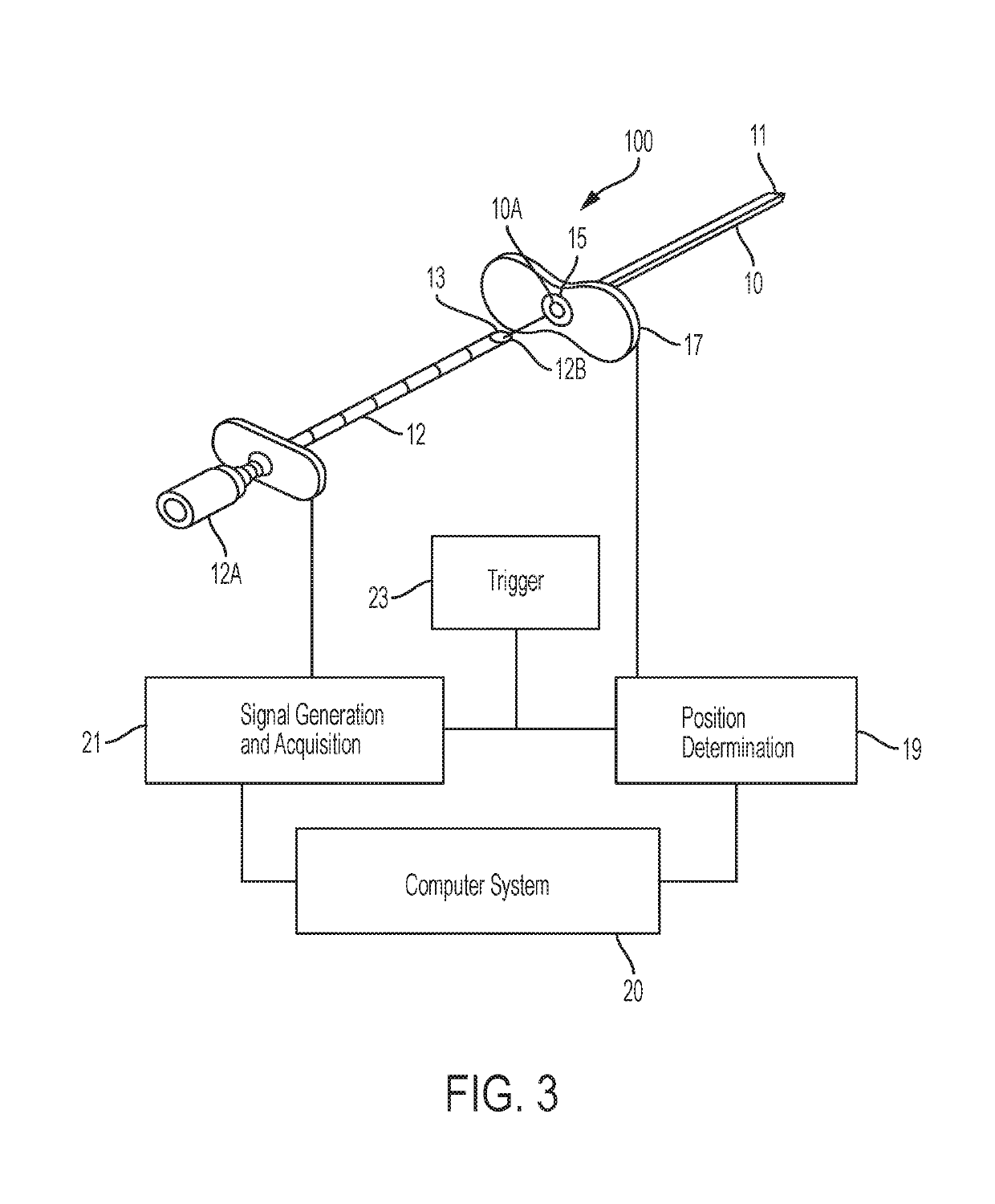
The present patent relates to a device or system for placing a needle in a body using ultrasound. The system includes an ultrasound transducer attached to the end of a needle, a needle constraining assembly that restricts the needle's movement to only rotational degrees of freedom within a certain range, and a needle sensor system that detects the angle at which the needle is oriented. The system can create synthetic aperture ultrasound images based on the detected needle angle and the ultrasound signals. The technical effects of the invention include improved accuracy and efficiency in placing needles in a body, especially in cases where the needle needs to be directed towards a specific location.

Problems solved by technology

This bending phenomenon becomes a serious issue amongst obese and obstetric patients, who have a thicker layer of adipose tissue.
In addition, hitting peripheral structures in multiple attempts leads to a myriad of complications including tissue trauma, pain, post dural puncture headaches (PDPH), CSF leaks, and traumatic, or bloody, taps.
Furthermore, physicians take an average of three attempts to collect CSF in a patient, and this can be even worse in obese and elderly patients.
Still, the procedure is almost always performed blindly without the assistance of any imaging modalities or techniques including CT or topical ultrasound.

Method used


Image

  • System for generating synthetic aperture ultrasound images during needle placement
  • System for generating synthetic aperture ultrasound images during needle placement
  • System for generating synthetic aperture ultrasound images during needle placement

Examples


Embodiment Construction

[0034]Some embodiments of the current disclosure are discussed in detail below. In describing embodiments, specific terminology is employed for the sake of clarity. However, the disclosure is not intended to be limited to the specific terminology so selected. A person skilled in the relevant art will recognize that other equivalent components can be employed and other methods developed without departing from the broad concepts of the current disclosure. All references cited anywhere in this specification, including the Background and Detailed Description sections, are incorporated by reference as if each had been individually incorporated.

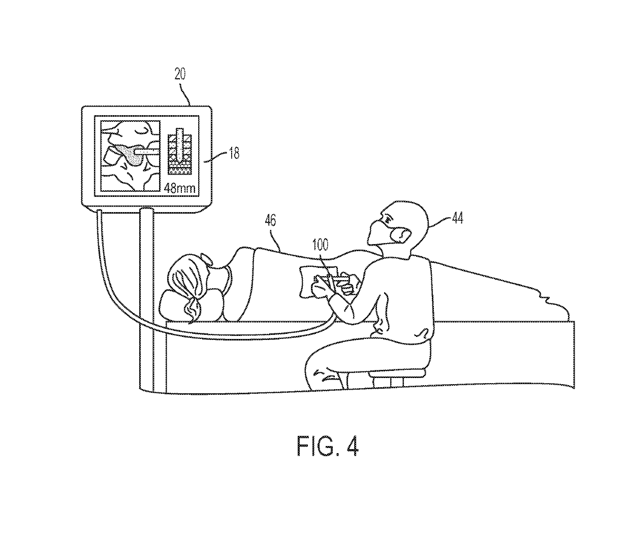
[0035]To aid clinicians performing deep needle placements (lumbar punctures, spinal anesthesia, epidurals, etc.), a system or device is provided to enable dynamic guidance in the form of ultrasound images to reduce iatrogenic complications and the chance of placement failure. In an embodiment, the device generates a high-resolution image from a sin...


PUM


Abstract

An aspect of the present disclosure is to provide a device or needle placement system including a needle having a proximal end and a distal end, and an ultrasound transducer element attached to the distal end of the needle. The system also includes a needle constraining assembly configured to receive and constrain the needle to only rotational degrees of freedom within a range of angular motion. The system further includes a needle sensor system incorporated into the constraining assembly to sense an angular orientation of the needle with the range of angular motion. The system also includes an ultrasound data processor configured to communicate with the transducer element to receive ultrasound detection signals and communicate with the needle sensor system to receive needle angular orientation signals. Based on the ultrasound detection and the needle angular orientation signals, the ultrasound data processor can calculate synthetic aperture ultrasound images.

Description

CROSS-REFERENCE TO RELATED APPLICATIONS[0001]This application claims priority benefit from U.S. provisional patent application No. 62 / 330,724, filed on May 2, 2016, the entire content of which is incorporated herein by reference. All references cited anywhere in this specification, including the Background and Detailed Description sections, are incorporated by reference as if each had been individually incorporated.BACKGROUND1. Field[0002]The field of the currently claimed embodiments of the present disclosure relates to needle placement systems and in particular to a system and a method for generating synthetic aperture ultrasound images during needle placement.2. Background[0003]Every year, over 400,000 lumbar punctures (LPs) are performed by neurologists and emergency medicine doctors to collect cerebrospinal fluid (CSF), a vital fluid in the diagnosis of many central nervous system diseases (CNS) and conditions. To perform this procedure, a physician palpates the lower back and ...

Claims


Application Information

Patent Timeline
Patent Type & Authority Applications(United States)
IPC IPC(8): A61B8/12A61B8/08A61B10/00A61B17/34A61B8/00A61B34/20
CPCA61B8/12A61B8/0841A61B10/0045A61B17/3403A61B8/5207A61B8/4483A61B34/20A61B2010/0077A61B2017/3413A61B2017/3405A61B2034/2059A61B2034/2063
Inventor PATEL, NISUSCALABRIN, ERNESTKANNAN, KARUNGUPTA, KUSHCHAN, LARISSAPAREDES, MATEOLIN, MELISSAROYCHOUDHURY, SHAYANSHAH, SURAJMOGHEKAR, ABHAYBOCTOR, EMAD M.DURR, NICHOLAS J.KIM, YOUNSUZHANG, HAICHONG K.
Owner THE JOHN HOPKINS UNIV SCHOOL OF MEDICINE
Learn More