
Method and system for mass arrangement of micro-component devices

a technology of micro-components and components, applied in the direction of fluid dynamics, semiconductor devices, electrical devices, etc., can solve the problems of time-consuming and difficult fabrication process of micro-led displays

Active Publication Date: 2019-04-18
MAVEN OPTRONICS CO LTD
View PDF0 Cites 8 Cited by
  • Summary
  • Abstract
  • Description
  • Claims
  • Application Information

AI Technical Summary

Benefits of technology

This patent describes a way to accurately and efficiently arrange micro-components into an array. This method and system can allow for the simultaneous arrangement of multiple micro-components, which was not previously possible using traditional pick-and-place methods. By using electromagnetic force to move the micro-components closer to each other, a precise and reproducible array can be created. Additionally, this method and system can be used to reduce the size of grid openings in the conductive wire assembly and control target gaps between micro-components. Furthermore, this method and system can directly transfer the array of micro-components from the liquid suspending medium to an application circuit board, eliminating the need for additional mass transfer processes.

Problems solved by technology

In addition, it is difficult to form a uniform thin film using an organic light-emitting material during the manufacturing process of OLED display devices, resulting in a so-called Mura effect.
Even though a micro-LED display device has the above-mentioned technical merits, however, when a large number of micro-LED chips sorted by similar electrical and optical properties are used to manufacture the display device, some technical challenges arise and should be overcome or improved.
For example, challenges arise in how to accurately arrange a large number of micro-LED chips into a micro-LED array to form a display device, how to transfer and electrically bond the array of micro-LEDs to a circuit board with a driving circuit to form a micro-LED display device, and the like.
Especially for high-resolution display devices, it may take more than a million micro-LED chips to be arranged and transferred, making the micro-LED display fabrication process challenging and time consuming.

Method used


Image

  • Method and system for mass arrangement of micro-component devices
  • Method and system for mass arrangement of micro-component devices
  • Method and system for mass arrangement of micro-component devices

Examples


Embodiment Construction

Definitions

[0025]The following definitions apply to some of the technical aspects described with respect to some embodiments of the disclosure. These definitions may likewise be expanded upon herein.

[0026]As used herein, the singular terms “a,”“an,” and “the” may include plural referents unless the context clearly dictates otherwise. Thus, for example, reference to a layer can include multiple layers unless the context clearly dictates otherwise.

[0027]As used herein, the term “set” refers to a collection of one or more components. Thus, for example, a set of layers can include a single layer or multiple layers. Components of a set also can be referred to as members of the set. Components of a set can be the same or different. In some instances, components of a set can share one or more common properties.

[0028]As used herein, the term “adjacent” refers to being near or adjoining. Adjacent components can be spaced apart from one another or can be in actual or direct contact with one a...


PUM


Abstract

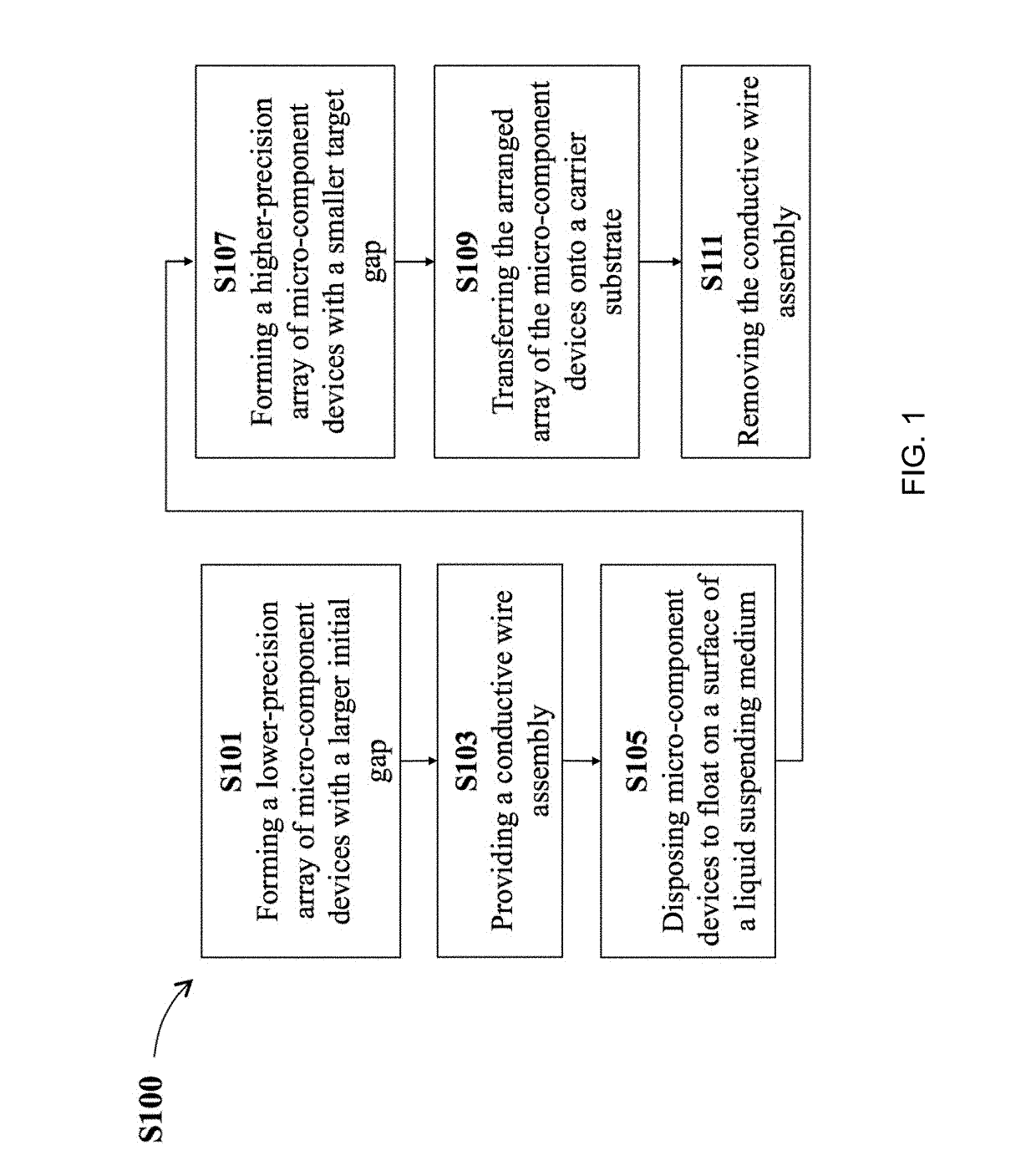
A method for mass arrangement of micro-component devices includes the following process stages: disposing the micro-component devices to float on a liquid suspending medium, wherein the micro-component devices are spaced apart from each other with a larger initial gap along a first direction and along a second direction; using electromagnetic force to actuate the floating micro-component devices to move closer so that the micro-component devices become spaced apart from each other with a smaller specified target gap along the first and the second directions; and transferring the arranged micro-component devices with the target gap on a carrier substrate. A system for arranging the micro-component devices is also disclosed to implement the method. Therefore, a precisely arranged array of the micro-component devices can be formed on a target application substrate.

Description

CROSS-REFERENCE TO RELATED APPLICATIONS[0001]This application claims the benefit of and priority to Taiwan Patent Application No. 106135119 filed on Oct. 13, 2017, and Chinese Patent Application No. 201710970476.1 filed on Oct. 16, 2017, the disclosures of which are incorporated herein by reference in their entirety.BACKGROUNDTechnical Field[0002]The present disclosure relates to a method and system for arranging component devices, and more particularly to a method and system for arranging a large number of micro-component devices.Description of the Related Art[0003]Light-emitting diodes (LEDs) have been developed for decades. In addition to traditional LED applications, such as indicator lights, illumination sources, backlight modules for liquid crystal displays (LCD), and outdoor large-scale display panels, applications of LEDs are now moving toward fine-pitch miniaturized LED (micro-LED) display devices. That is, through a semiconductor lithography process technology, the size of...

Claims


Application Information

Patent Timeline
Patent Type & Authority Applications(United States)
IPC IPC(8): H01L21/67H01L21/683F15D1/00
CPCH01L21/67121H01L21/6835F15D1/00H01L25/13H01L2224/83005H01L2224/83085H01L2224/83002H01L2224/95133H01L24/83H01L24/95H01L25/0753H01L2224/83192H01L2224/95001H01L2224/95085H01L2224/95136H01L2224/95146H01L2924/00014H01L2924/1461H01L2224/75101H01L2924/12041H01L2224/95144H01L25/167H01L2224/13099H01L2224/05599
Inventor CHEN, CHIEH
Owner MAVEN OPTRONICS CO LTD
Learn More