
Thrombectomy microcatheter

a micro-catheter and thrombosis technology, applied in the field of thrombosis micro-catheter, can solve the problems of downstream arteries with clot fragments, foregoing techniques, damage to arterial walls,

Inactive Publication Date: 2010-11-30
CFD RES CORP
View PDF36 Cites 27 Cited by
  • Summary
  • Abstract
  • Description
  • Claims
  • Application Information

AI Technical Summary

Benefits of technology

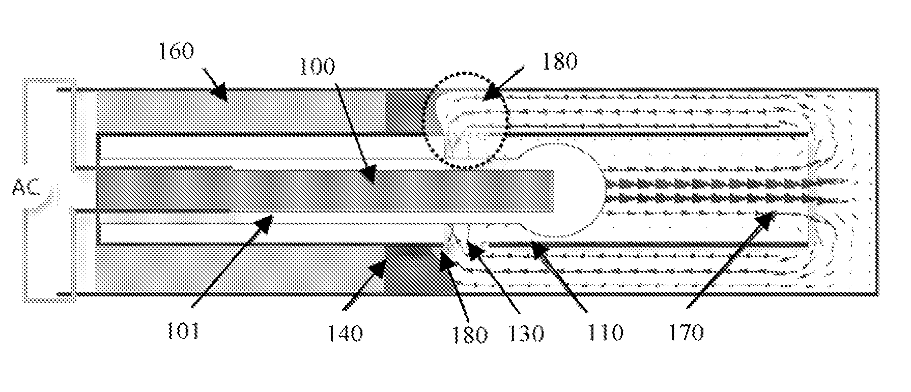
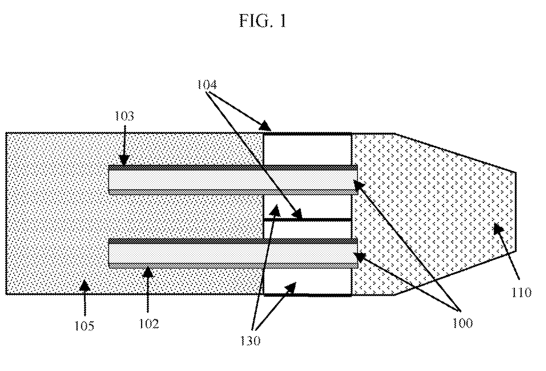
"The present invention is an ultrasonic thrombectomy catheter that can remove blockages in small arteries and vessels without damaging the arterial walls. The catheter uses microfabricated piezo fibers to generate strong fluidic motion to emulsify the blockage. The catheter has a distal opening and an open gap proximal to the distal end of the catheter head to allow the fluid stream to remove the blockage fragments. The catheter can have one or two lumens, with the second lumen serving as a drug delivery port for an anti-thrombotic agent. The invention can be used in various arteries and vessels, including the brain, heart, kidneys, and peripheral vessels."

Problems solved by technology

The foregoing techniques suffer from one or more the following drawbacks including damage to the arterial walls, blocking of smaller, downstream arteries with clot fragments, and catheter diameters limited to use in large arteries.
Laser devices and photo-acoustic devices in which light energy is converted into acoustic waves generate excessive heat and can perforate arterial walls.
Saline jets can cause vessel dissection.
Removing obstructions by suction can also damage arterial walls.
None of the devices described above use a piezo transducer positioned relative to a tube specifically to generate a tube effect resulting in acoustic streaming.
Pulsing the laser causes the repeated rapid formation and collapse of gas bubbles in liquid and generates excess heat in the process.
Acoustic streaming has thus far been incapable of generating shear forces strong enough to disrupt clots in small vessels.

Method used


Image

  • Thrombectomy microcatheter
  • Thrombectomy microcatheter
  • Thrombectomy microcatheter

Examples


example 1

Piezo Fiber Testing

[0039]In-vitro experiments were conducted using a single piezo fiber transducer. The experiments were carried out by placing the piezo fiber in a rectangular flow chamber. Fluorescent microparticles suspended in deionized (DI) water, were used as tracers for flow visualization. A signal generator was used to drive the piezo transducer and an AC signal was modulated with a commercial voltage amplifier. An inverted epi-fluorescence microscope was used to visualize the flow inside the chamber generated by the piezo transducer. A high performance high speed digital CCD camera was used to record the flow. Since the camera exposure time is known, the recorded path lines of the microparticles were measured to estimate flow velocity. Experimental results demonstrated that the piezo transducer generates acoustic streaming, and the corresponding flow rate can been increased by manipulating the transducer relative to a small tube. The forcing frequency and voltage for the ex...

example 2

Effect of Applied Voltage

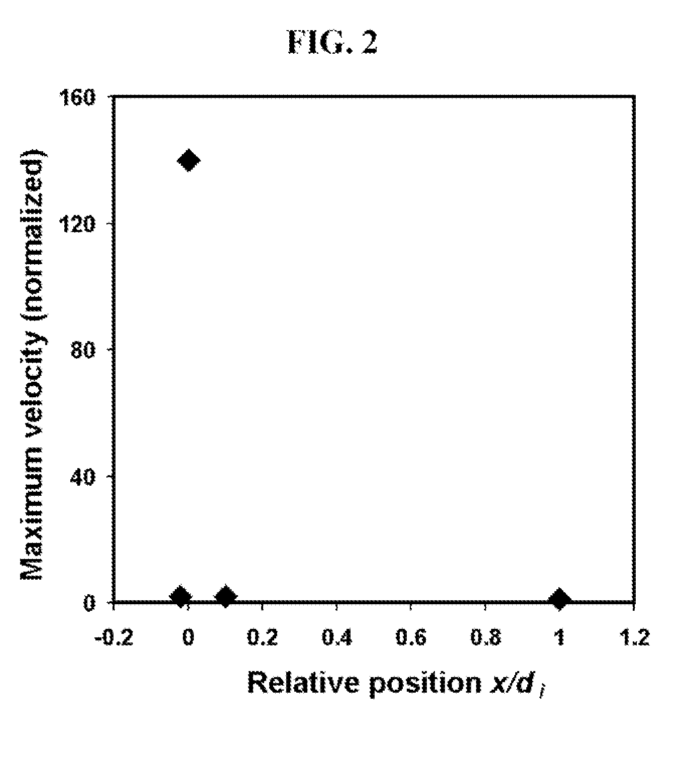
[0042]FIG. 12 shows the acoustic streaming in response to different applied voltages at the resonance frequency (42 kHz) obtained from the frequency characterization experiments. The maximal velocity scales with the applied voltage. The maximum streaming observed for a particular transducer depends on the piezo fiber size, its quality, and the insulation coating.

example 3

Piezo Fiber Coatings

[0043]Thinner coatings are more effective in transmitting the vibrational energy from the transducer to the surrounding fluid. Coating thickness optimally ranges from 10 μm to 50 μm and should be uniform along the length of the transducer. The stiffness of the insulation material also affects the oscillation of the transducer with lower stiffness being preferred.

[0044]Computational simulations were carried out to identify optimal choices for coating material. FIG. 13 shows the effects of coating, material stiffness on the vibrational amplitude of a transducer. As the coating layer becomes stiffer the vibration magnitude is seen to decrease non-linearily for a given frequency. The dampening of piezo motion is significant for Ec / Epiezo>0.5, with E being the Young modulus of elasticity and the subscripts c and piezo denote the coating and the transducer material properties. Therefore, coating materials softer than the piezo material preferred as insulation materials...


PUM


Abstract

The present invention is an ultrasonic thrombectomy catheter that produces physical forces (shear rates) strong enough to emulsify obstructions such as thrombi and emboli without causing damage to arterial walls. This is accomplished by properly arranging piezoelectric transducers within a catheter and a tubular catheter head separated by a gap to generate acoustic streaming that simultaneously emulsifies the obstruction and sweeps resulting debris into a catheter lumen for removal. The open gap may be formed by supporting struts that connect the catheter to the catheter head. The design of the catheter tip allows the fabrication of catheters capable of removing partial or complete blockages from arteries and other vessels having diameters as small as 2 mm.

Description

STATEMENT REGARDING FEDERALLY SPONSORED RESEARCH OR DEVELOPMENT[0001]The U.S. Government may have certain rights in this invention pursuant to SBIR Contract Number: NIH IR43NS050011-01 awarded by the National Institutes of Health.CROSS-REFERENCE TO RELATED APPLICATIONS[0002]Not ApplicableINCORPORATED-BY-REFERENCE OF MATERIAL SUBMITTED ON A COMPACT DISC[0003]Not ApplicableBACKGROUND OF THE INVENTION[0004]1. Field of the Invention[0005]The present invention is an apparatus for removing a thrombus or other blockage from an artery or other vessel. More specifically, the apparatus comprises a microcatheter containing a micro piezo electric fiber that generates shear flows capable of disrupting and removing blood clots in small blood vessels that are difficult or impossible to reach with conventional thrombectomy catheters. The shear forces required for thrombus disruption are produced through a tube effect created by the positioning of one or more piezo transducers relative to the openin...

Claims


Application Information

Patent Timeline
Patent Type & Authority Patents(United States)
IPC IPC(8): A61B17/22
CPCA61B17/2202A61B2017/00778A61B2017/22001A61B2017/22021
Inventor WANG, GUIRENSUNDARAM, SHIVSHANKARPANT, KAPILFENG, JIANJUNSTORM, PETER
Owner CFD RES CORP
Learn More