Brake control apparatus and brake control method

a technology of brake control and control apparatus, which is applied in the direction of braking system, failure-safe aspects, vehicle sub-unit features, etc., can solve the problem of conventional brake system operating in a fallback mod

Active Publication Date: 2019-04-04
HL MANDO CORP
View PDF4 Cites 4 Cited by
  • Summary
  • Abstract
  • Description
  • Claims
  • Application Information

AI Technical Summary

Benefits of technology

The present disclosure provides a brack control method that can detect if the braking device for a vehicle is malfunctions and instantly activate the vehicle's engine control module, motor control module, and parking brake control module to provide an auxiliary braking force. This helps to prevent accidents and ensures safe driving.

Problems solved by technology

Meanwhile, a conventional brake system operates in a fallback mode when a brake apparatus under the brake systems does not operate normally.

Method used


Image

  • Brake control apparatus and brake control method
  • Brake control apparatus and brake control method
  • Brake control apparatus and brake control method

Examples


Embodiment Construction

[0034]Hereinafter, embodiments of the present disclosure will be described in detail with reference to the accompanying drawings. The embodiments to be described below are provided to fully convey the spirit of the present disclosure to those skilled in the art. The present disclosure is not limited to the embodiments disclosed herein and may be implemented in other forms. In the drawings, some portions not related to the description will be omitted and not be shown to clearly describe the present disclosure, and sizes of components may be somewhat exaggerated to facilitate understanding.

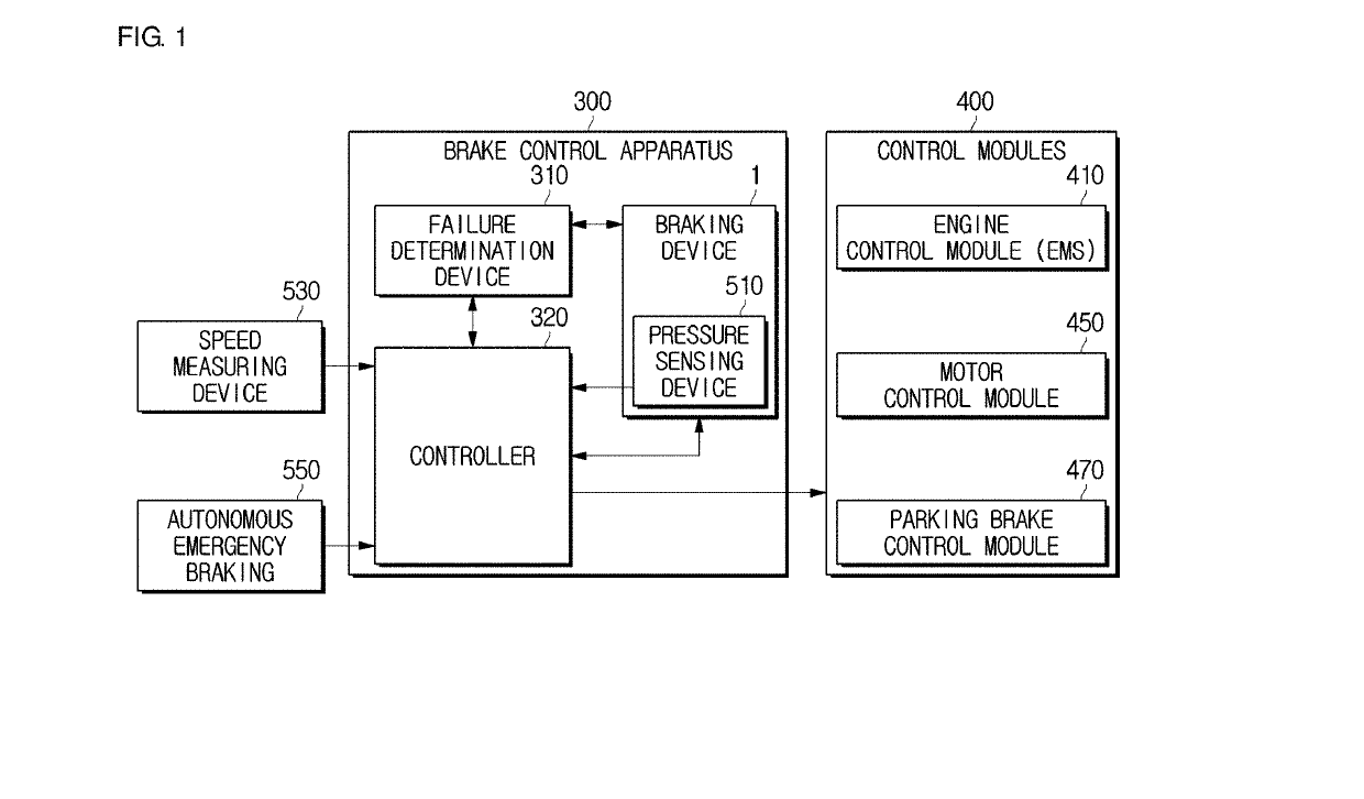
[0035]FIG. 1 is a block diagram of a brake system including a brake control apparatus according to an embodiment.

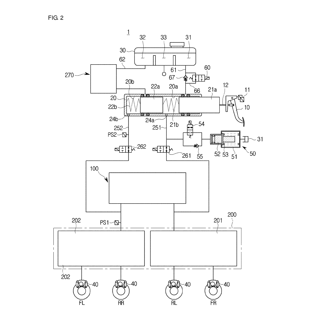
[0036]Referring to FIG. 2, a brake system may include a speed measuring device 530, autonomous emergency braking 550, a brake control apparatus 300, and control modules 400.

[0037]First, the speed measuring device 530 may calculate the speed of a vehicle to obtain information such as wheth...


PUM


Abstract

A brake control apparatus according to an embodiment of the present disclosure includes a braking device configured to generate a braking pressure based on a hydraulic pressure to provide a main braking force to a vehicle; and a controller configured to control at least one control module selected based on the speed of the vehicle among a plurality of control modules including an engine control module (EMS) of the vehicle, a motor control module and a parking brake control module to provide an auxiliary braking force to the vehicle when the braking device is in an abnormal state.

Description

CROSS-REFERENCE TO RELATED APPLICATION(S)[0001]This application is based on and claims priority under 35 U.S.C. § 119 to Korean Patent Application No. 10-2017-0127397, filed on Sep. 29, 2017 in the Korean Intellectual Property Office, the disclosure of which is incorporated by reference in its entirety.BACKGROUND1. Technical Field[0002]Embodiments of the present disclosure relate to a brake control apparatus and a brake control method, and more particularly, to a brake control apparatus and a brake control method configured to secure a braking force when a brake system fails.2. Description of the Related Art[0003]A brake system for braking is necessarily equipped in a vehicle, and a variety of systems for providing stronger and more stable braking have been proposed recently.[0004]For example, there are brake systems including an anti-lock brake system (ABS) for preventing a wheel from sliding while braking, a brake traction control system (BTCS) for preventing a drive wheel from sl...

Claims


Application Information

Patent Timeline
IPC IPC(8): B60W50/02B60T7/12B60T8/17B60T8/72B60W10/06B60W10/08B60W10/18B60W30/18
CPCB60W50/02B60T7/12B60T8/17B60T8/72B60W10/06B60W10/08B60W10/182B60W30/18109B60T2270/402B60T2250/04B60W2520/10B60W2710/06B60W2710/08B60W2710/18B60W2510/182B60T7/042B60T8/4081B60T13/662B60T13/745B60T2270/40B60T7/18B60T13/686B60T17/22B60T17/221B60T2220/04B60T2260/08B60T8/885B60W10/18B60W2540/00B60W2540/215B60W2720/106B60T8/32B60Y2400/306B65D1/36B65D11/20B65D2203/00
Inventor KIM, JONG WOOK
Owner HL MANDO CORP
Why Eureka
Try Eureka