System and Method for Intelligent Flow Control System for Production Cementing Returns

a flow control system and flow control technology, applied in the field of intelligent flow control system for cementing production, can solve the problems of unplanned and unwanted gas entry, unsafe conditions, and release into the atmospher

Active Publication Date: 2019-03-28
SPM OIL & GAS PC LLC
View PDF21 Cites 3 Cited by
  • Summary
  • Abstract
  • Description
  • Claims
  • Application Information

AI Technical Summary

Problems solved by technology

A gas kick is an unscheduled and unwanted entry of gas into the wellbore, which travels up the well and rapidly expands due to change in atmosphere pressure in an uncontrolled fashion.
Serious conseque...

Method used


Image

  • System and Method for Intelligent Flow Control System for Production Cementing Returns
  • System and Method for Intelligent Flow Control System for Production Cementing Returns

Examples


Embodiment Construction

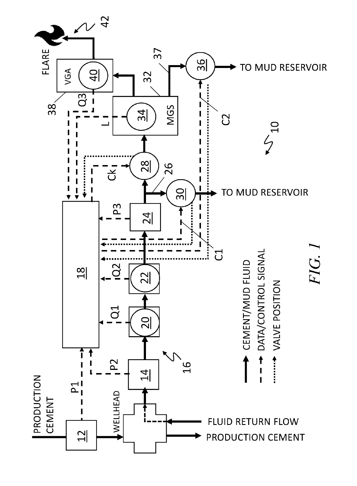
[0007]FIG. 1 is a diagram of an exemplary system and method 10 for controlling and monitoring wellbore fluid flow out of a wellhead during production cementing operations according to the teachings of the present disclosure. As shown in FIG. 1, during cementing operations, production cement slurry is introduced and pumped down into a wellhead between the wellbore and the casing, and the cement slurry displaces the drilling mud or fluid in the well and pushes it back up through the casing. The system and method 10 described herein are used to monitor the mud fluid that is returned back up the well to the drilling mud system. The system 10 includes a pressure sensor 12 that measures the fluid pressure (P1) of the inbound cement flurry, and a second pressure sensor 14 that measures the fluid pressure (P2) of the drilling fluid return flow in the primary return conduit 16. Additional pressure sensors may be used in addition to sensors 12 and 14 to provide for redundancy and backup. The ...


PUM


Abstract

A system and method of controlling and monitoring a cementing process injecting a cement slurry down a well that causes a return of a drilling fluid includes a first and second flowmeters disposed in the primary return conduit configured to generate a flow rate measurements of the returned drilling fluid, a first control valve receiving control signals from a microprocessor to regulate conducting the returned drilling fluid to a reservoir, a choke valve disposed downstream from the first and second flowmeters receiving control signals from a microprocessor to regulate diverting the returned drilling fluid in the primary return conduit in response to a detection of the presence of gas in the returned drilling fluid, and a mud-gas separator disposed in the primary return conduit configured to receive the diverted drilling fluid and separate the diverted drilling fluid into a mud component for return to the reservoir and a gas component for controlled burn off.

Description

RELATED APPLICATION[0001]The present application claims the benefit of U.S. Provisional Patent Application No. 62 / 561,908 filed on Sep. 22, 2017, incorporated herein by reference.FIELD[0002]The present disclosure relates to fluid flow control systems and methods, and in particular, to a system and method for intelligent flow control and monitoring during production cementing returns.BACKGROUND[0003]In oil and gas production, cement is used to hold the casing in place and to prevent fluid migration between subsurface formations. “Cementing,” one of the most critical steps, is the process of pumping a slurry of cement, cement additives, and water down through the casing to critical points in the annulus around the casing or in the open hole below the casing string. The cement slurry flows to the bottom of the wellbore through the well casing and displaces the drilling fluids still located within the well and allows the drilling fluids to come back up the well. The cement slurry flows ...

Claims


Application Information

Patent Timeline
IPC IPC(8): E21B21/08G01F1/05E21B21/06E21B41/00
CPCE21B21/08G01F1/05E21B21/063E21B41/00E21B47/06G01F1/66G01F1/44G01F1/84E21B21/10E21B21/067E21B33/14
Inventor GREEN, MATTHEW BRADY
Owner SPM OIL & GAS PC LLC
Why Eureka
Try Eureka