
Stress control cones for downhole electrical power system tubing encapsulated power cables

a technology of stress control cone and power cable, which is applied in the direction of cables, coupling device connections, borehole/well accessories, etc., can solve the problems of improper or incorrect termination, difficulty in properly cutting and preparing cables, and corrosion of fluid filled environmen

Active Publication Date: 2019-03-21
ARTIFICIAL ELEVATOR
View PDF0 Cites 245 Cited by
  • Summary
  • Abstract
  • Description
  • Claims
  • Application Information

AI Technical Summary

Benefits of technology

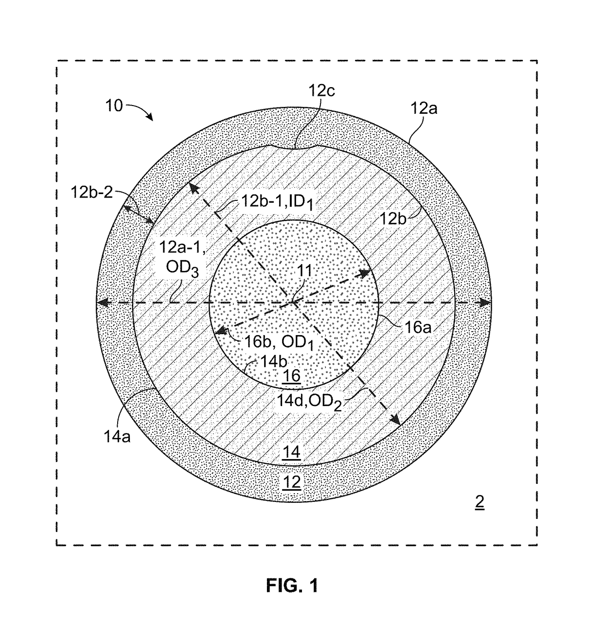
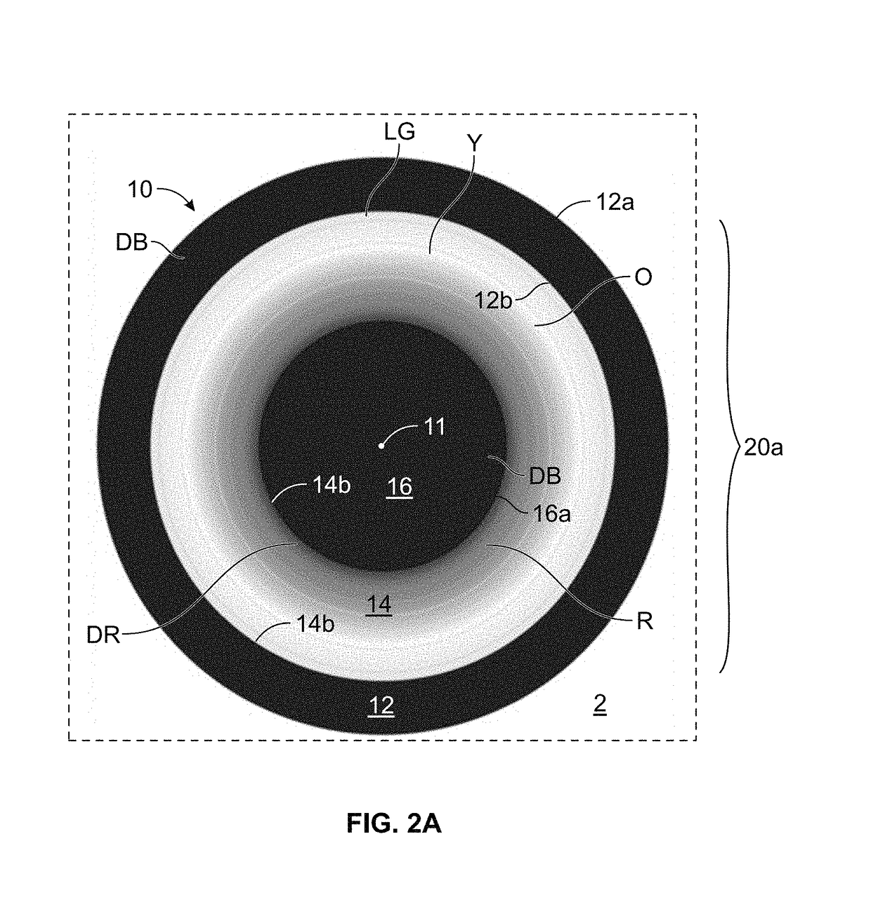
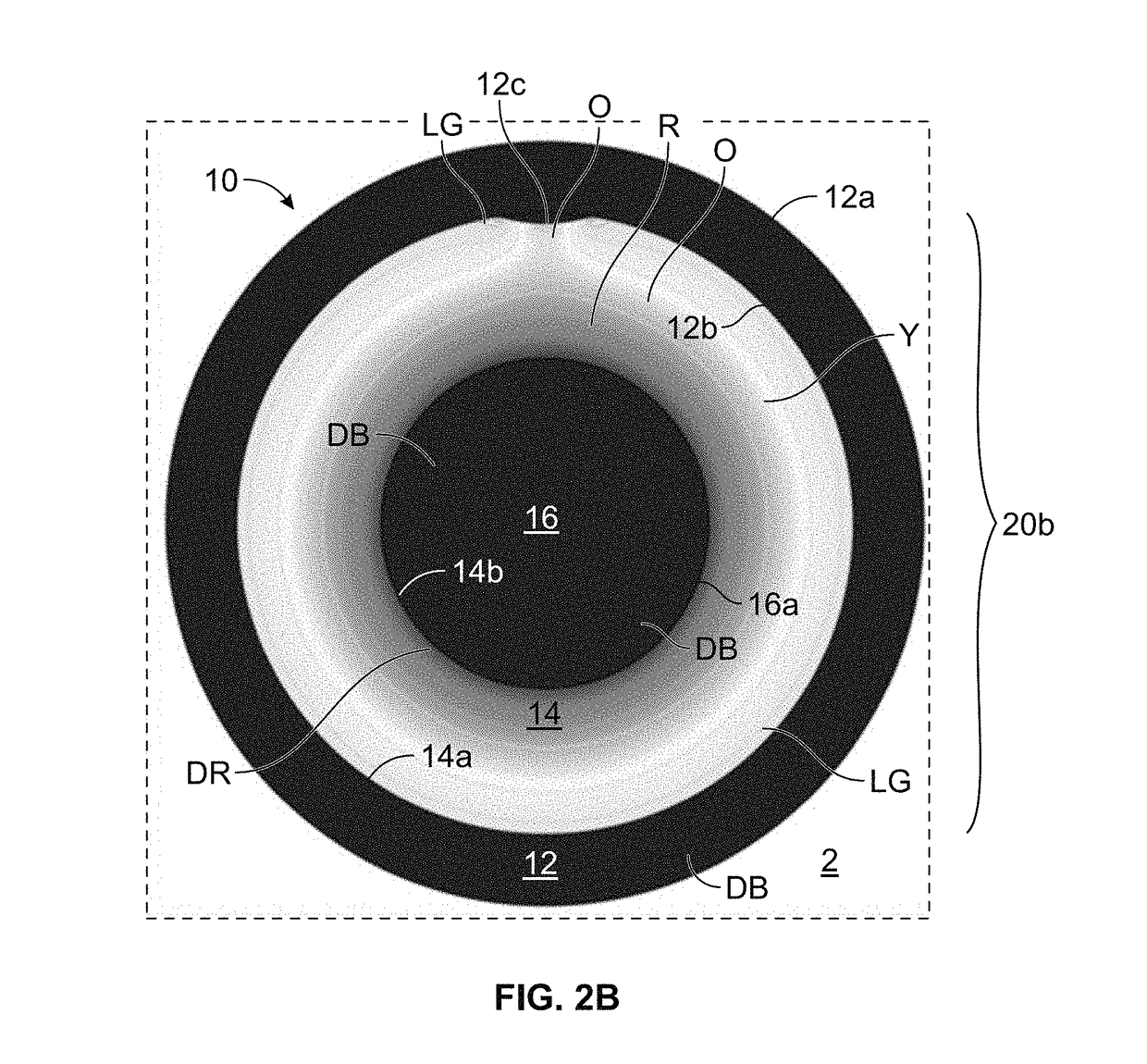
A stress cone is a device used to reduce electrical stresses in the area of the termination of a transmission electrical positioning system (TEPS) used in subsurface wells. It consists of an annular section that receives the terminated end of the TEPS and an insulation chamber that aligns with the first section to encase the insulated conductor core of the TEPS. The insulation material surrounds the core within the insulation chamber, which results in a smooth transition surface and a reduction of electrical stresses. The technical effect of this device is to improve the reliability and durability of the TEPS system in harsh environments of subsurface wells.

Problems solved by technology

Typically, a male / female connector is employed that enables the connection between power supply and ESP to be made-up remotely, so that it is operable in the harsh conditions of an oil-well, where high pressures and temperatures are present, and the fluid filled environment may be corrosive.
However, terminations of cables, such as terminating a power cable into another component such as a connector housing, present challenges in properly cutting and preparing the cable for establishing a reliable connection to another component.
Improper or incorrect termination may generate unintended leak paths and corrosion due to contamination by wellbore fluid as well as creating potential concentrations of electrical stresses due to non-uniform cable cutting.
ESP power systems (ESP cables and the associated connectors and feed-throughs) are very complex, long (typically 5,000 ft) power delivery systems that must withstand very high voltages (typically 5 KVAC phase to phase) over long periods of operation (10+ years) in a high temperature, high pressure environment (producing wellbore).
In addition, ESP cables are subjected to extreme mechanical stress during installation and operation.
Although these barriers can be effective in isolating the insulation from the damaging fluids, they are highly susceptible to damage in that they are soft, easy to tear, and hard to terminate.
ESP power system failures often occur at the termination of the protective sheath or where the sheath is not present (e.g., at connectors, splices, feed-throughs, and sites of mechanical damage to sheath).
Past attempts have been made to use a robust sheath (metallic tube instead of lead) but these have failed for several reasons.
For example, traditionally, the metallic sheath of TEPC is very difficult to terminate in the field, making installation in the field impractical.
Additionally, another source of failure is the voltage stress induced by the metallic sheath in high voltage applications leading to premature failure.
The replacement of a failed ESP system will typically cost $300 K to $15 MM, not including the cost of the lost production while the ESP system is non-operational (it can take up to one year to replace).
This cost represents a huge burden on oil and gas operations.

Method used


Image

  • Stress control cones for downhole electrical power system tubing encapsulated power cables
  • Stress control cones for downhole electrical power system tubing encapsulated power cables
  • Stress control cones for downhole electrical power system tubing encapsulated power cables

Examples


Embodiment Construction

[0063]Reference throughout the specification to “one embodiment,”“an embodiment,”“some embodiments,”“one aspect,”“an aspect,” or “some aspects” means that a particular feature, structure, method, or characteristic described in connection with the embodiment or aspect is included in at least one embodiment of the present disclosure. Thus, the appearance of the phrases “in one embodiment” or “in an embodiment” or “in some embodiments” in various places throughout the specification are not necessarily all referring to the same embodiment. Furthermore, the particular features, structures, methods, or characteristics may be combined in any suitable manner in one or more embodiments. The words “including” and “having” shall have the same meaning as the word “comprising.”

[0064]Moreover, inventive aspects lie in less than all features of a single disclosed embodiment. Thus, the claims following the Detailed Description are hereby expressly incorporated into this Detailed Description, with e...


PUM


Abstract

A stress cone for reducing electrical stresses is disclosed for use on terminated ends of tubing encapsulated power cable used in surface applications in a subsurface well power system employing electric submersible pumps (ESPs). The stress cone comprises an annular section about a longitudinal axis for receiving a terminated end of the TEPC in its first end and for abutting the terminated metal TEPC end against a metal shoulder at its second end therein, and an insulation chamber axially aligned with and connected to the annular section. The chamber comprises a metal interior surface symmetrical about the axis. The insulated TEPC core (without outer metal sheath) passes through the insulation chamber along the axis and then exits. The ID of the TEPC metal sheath and the inside metal surface of the chamber form a smooth ground plane transition surface. Insulation material surrounds the TEPC insulation layer within the insulation chamber.

Description

CROSS-REFERENCE TO RELATED APPLICATIONS[0001]This application claims the benefit of the filing date of and priority to: U.S. Provisional Application Ser. No. 62 / 561,658 entitled “Stress Control Cones for Downhole Electrical Power System Tubing Encapsulated Power Cables” and filed Sep. 21, 2017, Confirmation No. 2891; said provisional application is incorporated by reference herein in its entirety for all purposes.STATEMENT REGARDING FEDERALLY SPONSORED RESEARCH OR DEVELOPMENT[0002]Not Applicable.BACKGROUND OF THE INVENTION[0003]The following descriptions and examples are not admitted to be prior art by virtue of their inclusion in this section.[0004]Hydrocarbon fluids such as oil and natural gas are obtained from a subterranean geologic formation, referred to as a reservoir, by drilling a well that penetrates the hydrocarbon-bearing formation. In some cases, a lack of formation pressure or the viscosity of the hydrocarbon produced from the formation (among other reasons) require the...

Claims


Application Information

Patent Timeline
IPC IPC(8): H02G15/064H01B7/04H01R13/533H01R9/05E21B43/12
CPCH02G15/064H01B7/046H01B7/20E21B43/128H01R13/533H01R9/05E21B17/023H01R13/523E21B17/0285
Inventor MALONE, DAVIDLEISMER, DWAYNECANTU, ROGELIOJANERT, STEPHEN
Owner ARTIFICIAL ELEVATOR
Learn More