
Accumulator control device and method for micro gas turbine

A micro gas turbine and control device technology, applied in battery circuit devices, circuit devices, adaptive control, etc., can solve the problems of battery dehydration, battery permanent damage, low charging efficiency, etc.

Inactive Publication Date: 2006-11-08
NORTHEASTERN UNIV
View PDF0 Cites 9 Cited by
  • Summary
  • Abstract
  • Description
  • Claims
  • Application Information

AI Technical Summary

Problems solved by technology

The traditional charging method of the storage battery, whether it is the constant voltage charging method or the constant current charging method, the initial charging current is always lower than the battery's acceptance capacity, resulting in low charging efficiency and long charging time, and in the later stage of charging, the final charging The current is always higher than the battery's acceptance capacity, so the gas evolution rate in the battery continues to increase until the charging is close to the end, and all the charging current is supplied to the gas evolution
Moreover, if the charging voltage is set too high, the rate of oxygen generated by the positive electrode is too fast, and the absorption rate cannot keep up with the rate of oxygen generation. After a long time, the battery will inevitably lose water, thereby inducing failure phenomena such as micro-short circuit and sulfation of the battery. , damage the quality and service life of the battery
At the same time, the polarization of the battery during high-speed charging will cause the internal pressure of the battery to rise, the temperature of the battery to rise, and the internal resistance of the battery to rise, etc., which will not only shorten the life of the battery, but may also cause permanent damage to the battery
Therefore, the traditional charging method is not a good charging technology either from the perspective of efficiency or safety.

Method used


Image

  • Accumulator control device and method for micro gas turbine
  • Accumulator control device and method for micro gas turbine
  • Accumulator control device and method for micro gas turbine

Examples


Embodiment Construction

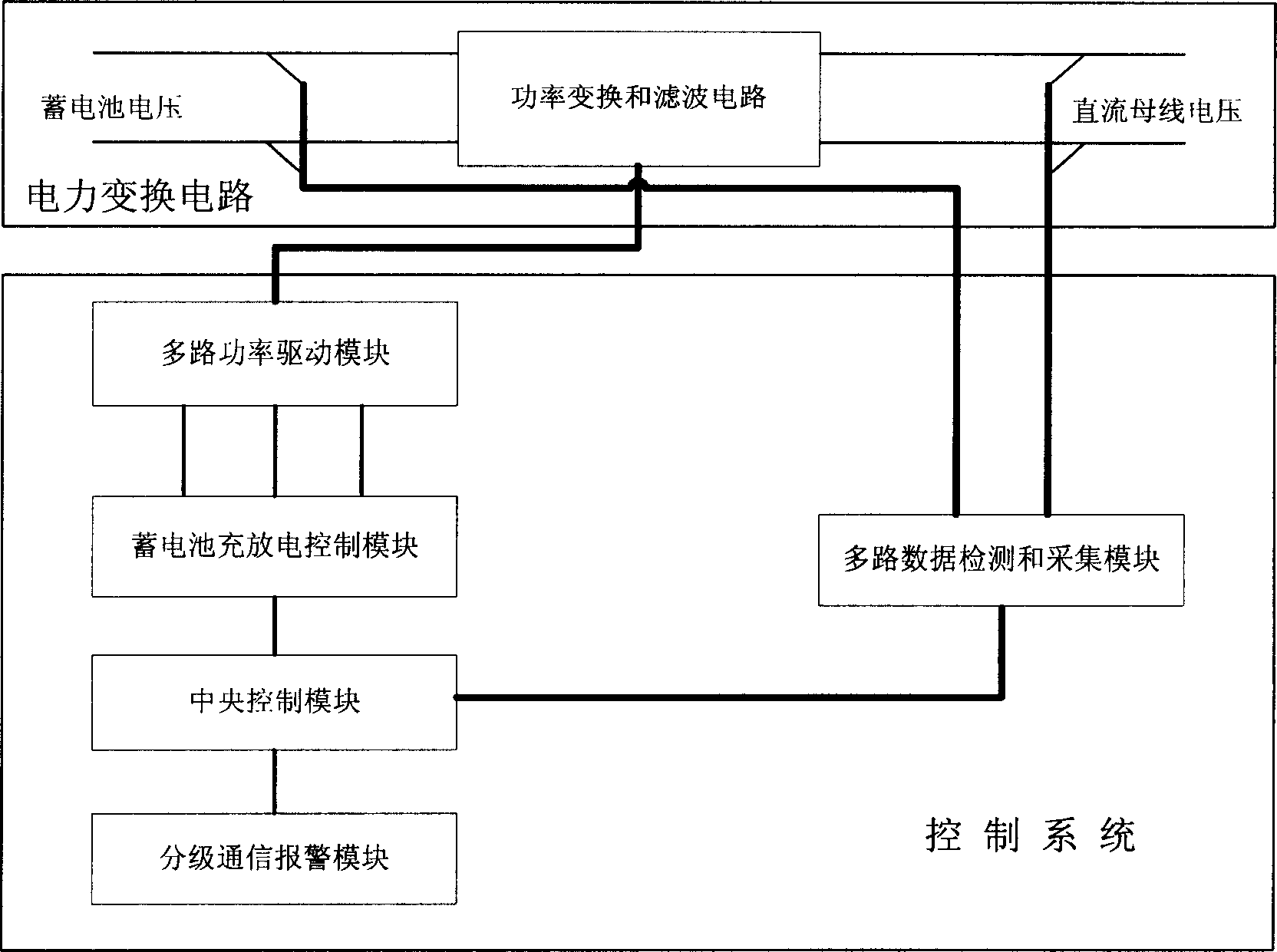
[0158] The device of the present invention is composed of two parts, a power conversion circuit and a control system, such as figure 1 shown. The power conversion circuit is a power conversion and filtering circuit; the control system includes a multi-channel power drive module, a multi-channel data detection and acquisition module, a central control module, a hierarchical communication alarm module, and a battery charge and discharge control module.

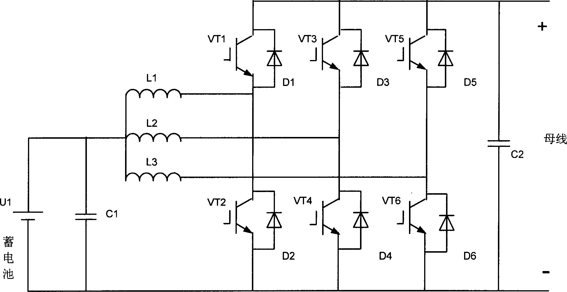
[0159] The power conversion and filter circuit is composed of six IGBTs, six freewheeling diodes, three inductors and two capacitors, and adopts a parallel and interleaved structure of three bridge arms, such as figure 2 shown. In the figure, a DC voltage is applied between the positive and negative voltages, and every two IGBTs and every two diodes connected between the positive and negative voltages form a unit (ie, a bridge arm) which is realized by a dual IGBT module, and an inductor is connected to each module .

[0160...


PUM


Abstract

This invention relates to a storage battery control device of a micro-gas turbine composed of a power commutation circuit and a control system, in which, the power commutatuin circuit is the power commutation and filter circuit, the control system includes a multiple power control module, a multiple data test and collection module, a central control module, a step communication alarm module and a charge and discharge control module of batteries, the power commutation and filter circuit is connected with the multi-power drive module, the multiple data test and collection module are connected with the two poles of the voltage of the battery and the DC bus, the multi-power drive module is connected with the charge-discharge control module, the central control module is connected with the charge-discharge control module, the multiple data test and collection module and the step communication alarm module, which is used in a micro-gas turbine generation system.

Description

technical field [0001] The invention belongs to the technical field of power electronics, and in particular relates to a storage battery control device and method for a micro gas turbine. technical background [0002] In order to make rational use of energy, micro gas turbine power generation systems have been used more and more. The fundamental reason for the development of micro-turbine heating, electricity and cooling systems lies in the consideration of energy saving and environmental protection factors. At the same time, there is also a crucial reason that these distribution systems will become an important part of the building energy system, providing power for the building. Security of supply is guaranteed. The generator sets distributed in the user end can make the building independent of the fragile power grid system and improve the safety factor of the building's own energy system. The battery management system is an important part of the self-developed micro gas...

Claims


Application Information

Patent Timeline
IPC IPC(8): H02J7/00G05B13/02H01M10/44
CPCY02E60/10
Inventor 张化光边春元陈宏志刘秀翀闫士杰李爱平韩安荣
Owner NORTHEASTERN UNIV
Learn More