Stabilizing operation of a high speed variable focal length tunable acoustic gradient lens in an imaging system

a high-speed variable and imaging system technology, applied in the field of precision metrology, can solve the problems of small, but non-negligible, measurement errors, and the operation conditions of the tag lens may drift, so as to facilitate the stabilization operation of the tag lens, reduce or eliminate the above-mentioned measurement errors, and stabilize the operation

Active Publication Date: 2019-03-07
MITUTOYO CORP
View PDF0 Cites 0 Cited by
  • Summary
  • Abstract
  • Description
  • Claims
  • Application Information

AI Technical Summary

Benefits of technology

[0007]An imaging system utilizing a TAG lens may be calibrated for its focal length or position as a function of phase timing during its resonant cycle, using known operating conditions for the calibration, e.g., while using a particular drive amplitude at a particular resonant frequency. During calibration, stable environmental conditions may be provided to ensure that the desired operating conditions are stable and known throughout the calibration data acquisition. After calibration, for a surface that produces a best-focused image when exposed using a particular phase timing, the calibration data may be used to indicate the focal position of that surface relative to the imaging system, which provides a measurement of its position or height. In operation, however, the operating conditions of a TAG lens may drift due to various factors, and may fail to precisely match the operating conditions used for calibration. This may result in small, but non-negligible, measurement errors. It is known that the resonant frequency of a TAG lens will slightly vary as a function of the lens temperature, for example. This reflects a change in the electro-mechanical response of the lens to the drive signal. It is also known that a change in the temperature of the lens fluid changes its nominal refractive index. Any such change in the electro-mechanical response of the lens and / or its fluid properties necessarily changes the optical power (or focal length) response of the lens to the drive signal, resulting in the aforementioned measurement errors. A need exists for techniques that facilitate stabilizing operation of a TAG lens (e.g., including its operating temperature), which will stabilize the operation of an imaging system including a TAG lens and allow the reduction or elimination of the aforementioned measurement errors.
[0010]The method and imaging system according to various embodiments are therefore capable of monitoring and stabilizing operation of a TAG lens and stabilizing operation of the imaging system that incorporates the TAG lens, during ongoing operation.

Problems solved by technology

In operation, however, the operating conditions of a TAG lens may drift due to various factors, and may fail to precisely match the operating conditions used for calibration.
This may result in small, but non-negligible, measurement errors.
Any such change in the electro-mechanical response of the lens and / or its fluid properties necessarily changes the optical power (or focal length) response of the lens to the drive signal, resulting in the aforementioned measurement errors.

Method used


Image

  • Stabilizing operation of a high speed variable focal length tunable acoustic gradient lens in an imaging system
  • Stabilizing operation of a high speed variable focal length tunable acoustic gradient lens in an imaging system
  • Stabilizing operation of a high speed variable focal length tunable acoustic gradient lens in an imaging system

Examples


Embodiment Construction

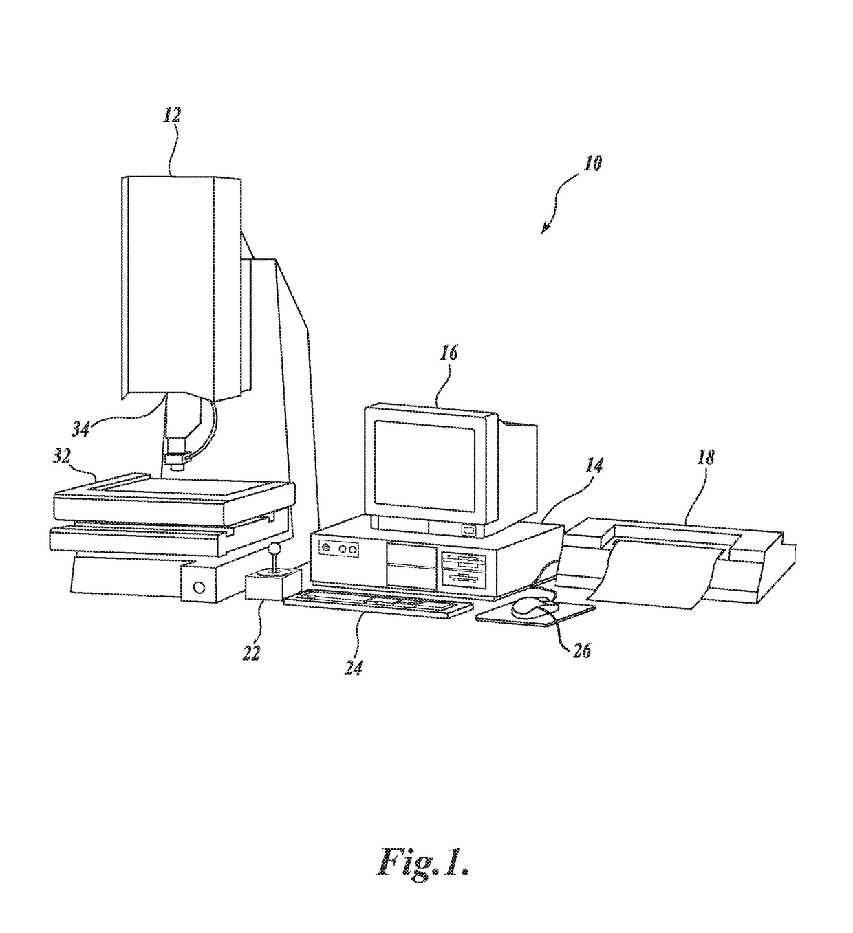
[0018]FIG. 1 is a block diagram of one exemplary machine vision inspection system 10 usable as an imaging system in accordance with methods described herein. The machine vision inspection system 10 includes a vision measuring machine 12 that is operably connected to exchange data and control signals with a controlling computer system 14. The controlling computer system 14 is further operably connected to exchange data and control signals with a monitor or display 16, a printer 18, a joystick 22, a keyboard 24, and a mouse 26. The monitor or display 16 may display a user interface suitable for controlling and / or programming the operations of the machine vision inspection system 10. It will be appreciated that in various implementations, a touchscreen tablet or the like may be substituted for and / or redundantly provide the functions of any or all of the computer system 14, the display 16, the joystick 22, the keyboard 24, and the mouse 26.

[0019]Those skilled in the art will appreciate...


PUM

PropertyMeasurementUnit
resonant frequencyaaaaaaaaaa

Abstract

A method is provided for operating an imaging system to maintain a tunable acoustic gradient (TAG) lens at a desired operating state. In a first step, the TAG lens operates using a standard imaging drive control configuration (e.g., a standard drive voltage and duration) during a plurality of imaging drive mode time periods, to achieve a standard imaging state of the TAG lens. In a second step, the TAG lens operates using a regulating adaptive drive control configuration during a plurality of regulating adaptive drive mode time periods, wherein at least one of a different respective TAG lens drive voltage and a different respective TAG lens drive duration is used for different respective regulating adaptive drive mode time periods, based on a monitoring signal that is indicative of a difference between the standard imaging state and a current operating state of the TAG lens.

Description

BACKGROUNDTechnical Field[0001]This disclosure relates to precision metrology using a high speed variable focal length lens (e.g., in a machine vision inspection system) and, more particularly, to monitoring and stabilizing operation of a high speed variable focal length lens in an imaging system.Description of the Related Art[0002]Precision non-contact metrology systems such as precision machine vision inspection systems (or “vision systems” for short) may be utilized to obtain precise dimensional measurements of objects and to inspect various other object characteristics, and may include a computer, a camera and optical system, and a precision stage that moves to allow workpiece traversal and inspection. One exemplary prior art system is the QUICK VISION® series of PC-based vision systems and QVPAK® software available from Mitutoyo America Corporation (MAC), located in Aurora, Ill. The features and operation of the QUICK VISION® series of vision systems and the QVPAK® software are...

Claims


Application Information

Patent Timeline
Patent Type & Authority Applications(United States)
IPC IPC(8): H04N5/232H04N5/235G02F1/29G02B7/28G03B13/36
CPCH04N5/23212H04N5/2352G02F2001/291G02F1/29G02F2203/18H04N5/23245G02B7/282G02F1/113G03B13/36H04N23/67G02F1/291H04N23/56H04N23/667H04N23/73H04N23/74H04N23/72
Inventor FREERKSEN, ISAIAHGLADNICK, PAUL GERARD
Owner MITUTOYO CORP
Why Eureka
Try Eureka