Guide-connected contactor and portable electronic device comprising same

Active Publication Date: 2019-03-07
AMOTECH
View PDF12 Cites 0 Cited by
  • Summary
  • Abstract
  • Description
  • Claims
  • Application Information

AI Technical Summary

Benefits of technology

The present invention provides a guide-connected contactor with various functions, including improving workability in manufacturing and being easily applied to various types of conductive cases. The guide-connected contactor can realize various functions without increasing the number of components or size of an electronic device. The technical effects of the invention include improved workability, versatility, and stability.

Problems solved by technology

However, since an electrical path may be formed between the external housing and the internal circuit board due to the conductive gasket or the conductive contactor, when static electricity having a high voltage is suddenly introduced through a conductor such as an external metal housing, the static electricity may be introduced into the internal circuit board through the conductive gasket or the conductive contactor, thereby causing damage to a circuit such as an integrated circuit (IC).
In addition, a leakage current generated by alternating current (AC) power may propagate to the external housing along a ground portion of the circuit so that a user may feel discomfort or, in a severe case, an electric shock accident causing injury to the user may occur.
Further, when the metal housing is used as an antenna, the conductive gasket or the conductive contactor is required to have a high capacitance because a signal attenuation that interrupts an RF signal transmission may occur when the capacitance is low.
Further, when a component provided in the form of a single module is installed in a portable electronic device, the electrical connection failure may occur more frequently at a connection portion between the single module and the portable electronic device than a connection portion between functional units constituting the single module.
In addition, when the functional contactor is coupled to a conductive case, a stable connection is required because soldering work is difficult, so the design change according to a shape of a groove of the conductive case may not be easily achieved depending on a coupling position, and the position selection is required with careful attention when performing coupling work, thereby frequently causing defects.

Method used


Image

  • Guide-connected contactor and portable electronic device comprising same
  • Guide-connected contactor and portable electronic device comprising same
  • Guide-connected contactor and portable electronic device comprising same

Examples


Embodiment Construction

[0054]Hereinafter, exemplary embodiments of the present invention will be described in detail with reference to the accompanying drawings such that those skilled in the art may easily implement the present invention. The present invention may be implemented in various forms and is not limited to the embodiments described herein. In the drawings, elements that do not relate to the present invention are omitted for clarifying the present invention, and the same reference numerals are assigned to the same or similar components throughout the specification.

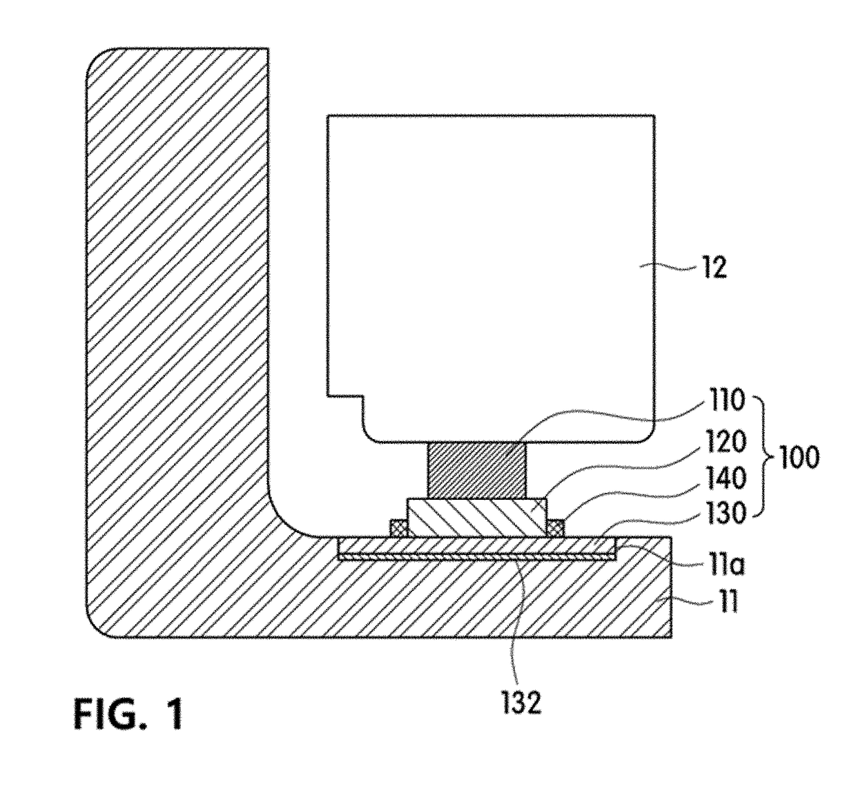
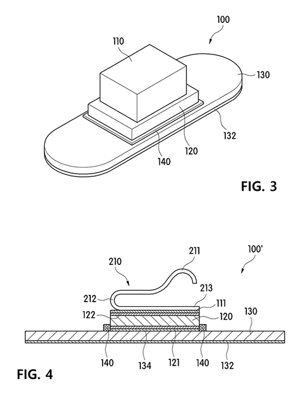
[0055]As shown in FIGS. 1 and 3, a guide-connected contactor 100 according to an embodiment of the present invention includes an elastic conductor 110, a functional element 120, and a guide 130.

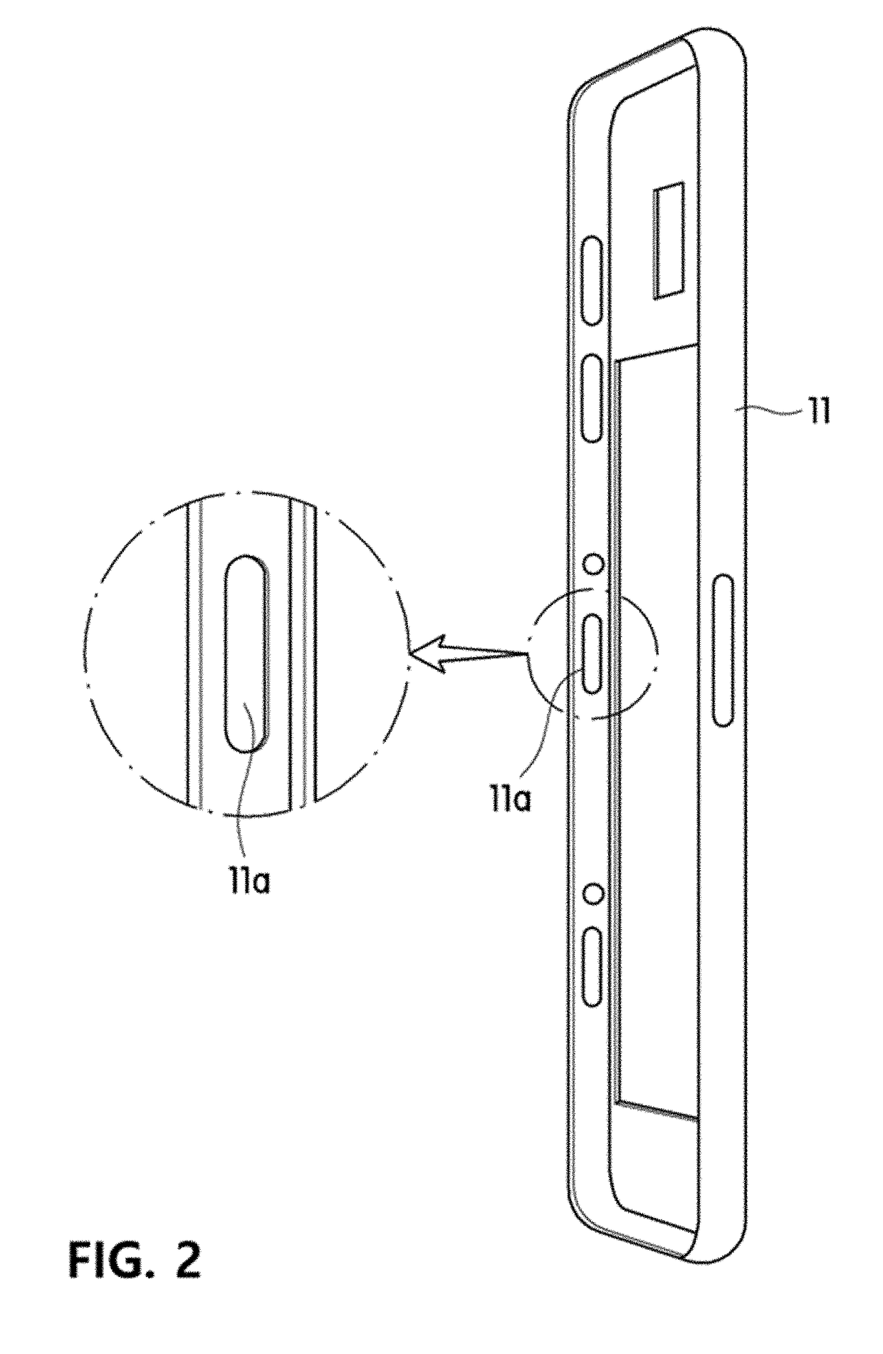
[0056]The guide-contact type contactor 100 is used to electrically connect a conductive case 11 such as an external metal case to a circuit board or a conductive bracket 12 in a portable electronic device.

[0057]The conductive bracket 12 may hav...


PUM


Abstract

Provided are a guide-connected contactor and a portable electronic device comprising same. A guide-connected contactor, according to an embodiment of the present invention, comprises: an elastic conductor which comes in contact with a circuit board of an electronic device or a bracket connected to the circuit board; a functional element which is connected to the elastic conductor and has a first electrode and a second electrode on the upper surface and the lower surface, respectively; and a guide which is plate-shaped, has the functional element connected thereto, and is connected to a groove portion provided on a conductive case of the electronic device.

Description

FIELD OF THE DISCLOSURE[0001]The present invention relates to a contactor for an electronic device such as a smart phone, and more specifically, to a guide-connected contactor capable of improving stability of connection, a degree of freedom in design, and processability of a contactor, and a portable electronic device including the same.DESCRIPTION OF RELATED ART[0002]Recently, housings formed of metals are increasingly used for portable electronic devices to improve aesthetics and robustness of the portable electronic devices. Such a portable electronic device includes a conductive gasket or a conductive contactor provided between an external housing and an internal circuit board of the portable electronic device to attenuate an impact from the outside, to reduce electromagnetic waves introduced into or propagated from the portable electronic device, and to electrically connect an antenna disposed in the external housing to the internal circuit board.[0003]However, since an electr...

Claims


Application Information

Patent Timeline
IPC IPC(8): H01C7/10H01G4/40H01R13/24H01R13/703H04M1/02H05K9/00
CPCH01C7/10H01G4/40H01R13/24H01R13/703H04M1/02H05K9/0079H05K9/0067H01R13/2414H01R13/6584H04M1/0202H04M1/0277H01R13/2428H01R13/7031
Inventor LIM, BYUNG GUKKONG, DONG HUNCHOI, JAE WOORYU, JAE SU
Owner AMOTECH
Why Eureka
Try Eureka