
Oxygenate reduction catalyst and process

a technology of oxygenate and catalyst, which is applied in the direction of catalyst regeneration/reactivation, physical/chemical process catalyst, biofuel, etc., can solve the problems of the inability to reduce the amount of oxygenate in the catalyst, so as to achieve less endothermic effects and more throughput of biomass

Active Publication Date: 2019-03-07
UNIVERSITY OF PRETORIA
View PDF9 Cites 0 Cited by
  • Summary
  • Abstract
  • Description
  • Claims
  • Application Information

AI Technical Summary

Benefits of technology

The invention relates to a method for producing high-quality pyrolysis-oil from bio-oil using a metal sulfide reduction-oxidation reaction. This can be done at pyrolysis conditions or in a liquid phase hydrothermal liquefaction system. The use of a catalyst reduces the amount of carboxylic acids and other impurities in the liquid oil. The catalyst also helps to increase the amount of carbon oxides produced, leading to a less endothermic process, and allows for more bio-mass to be processed through the system.

Problems solved by technology

Pyrolysis oil is difficult to process into more useful products mostly due to its high oxygen content.
The presence of oxygenated substituents in the pyrolysis oil causes it to be more polar, making it readily soluble with water as well as chemically unstable.
In particular, the bio-oil is quite high in oxygenates and has an unacceptable Carbon to Oxygen ratio and a very low Hydrogen to Carbon ratio, while also having a lower than required heating value.

Method used


Image

  • Oxygenate reduction catalyst and process
  • Oxygenate reduction catalyst and process
  • Oxygenate reduction catalyst and process

Examples


Embodiment Construction

[0054]The invention will now be described, by way of non-limiting example only, with reference to the accompanying diagrammatic drawings. In the drawings,

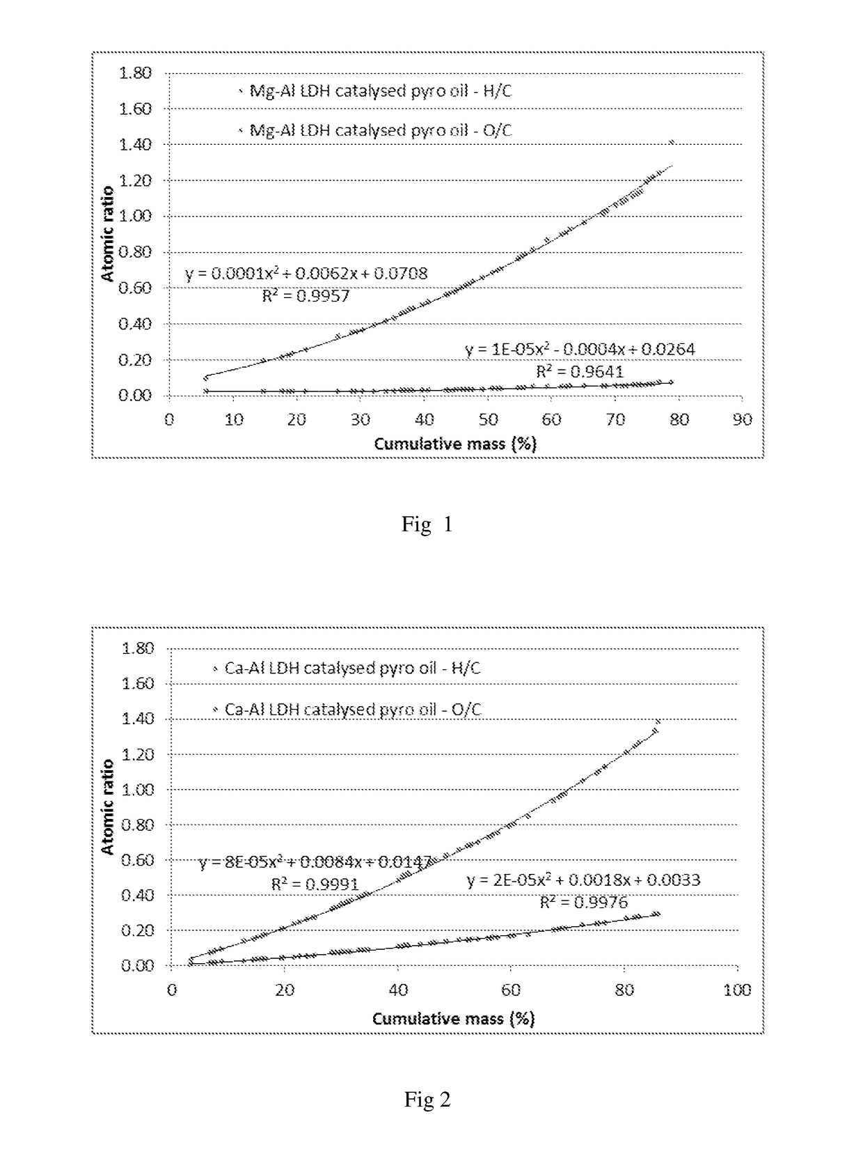
[0055]FIG. 1 shows the results of the pyrolysis oil deoxygenation for a Mg—Al LDH looping catalyst system;

[0056]FIG. 2 shows the results of the pyrolysis oil deoxygenation for a Ca—Al LDH looping catalyst system;

[0057]FIG. 3 shows the results of the pyrolysis oil deoxygenation for a zeolite catalyst system;

[0058]FIG. 4 shows comparative data to FIGS. 1 to 3 for an uncatalysed pyrolysis production of pyrolysis oil;

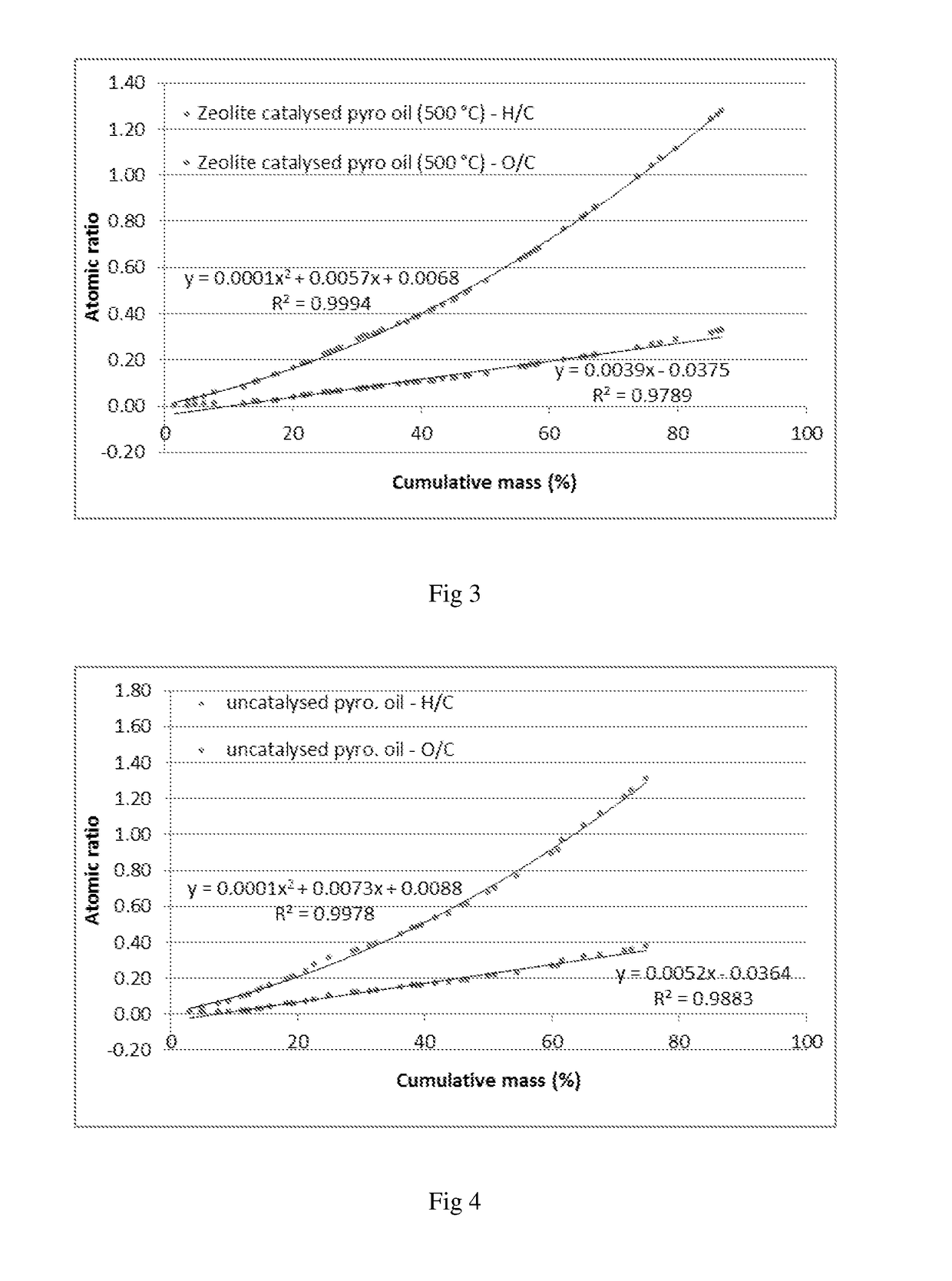
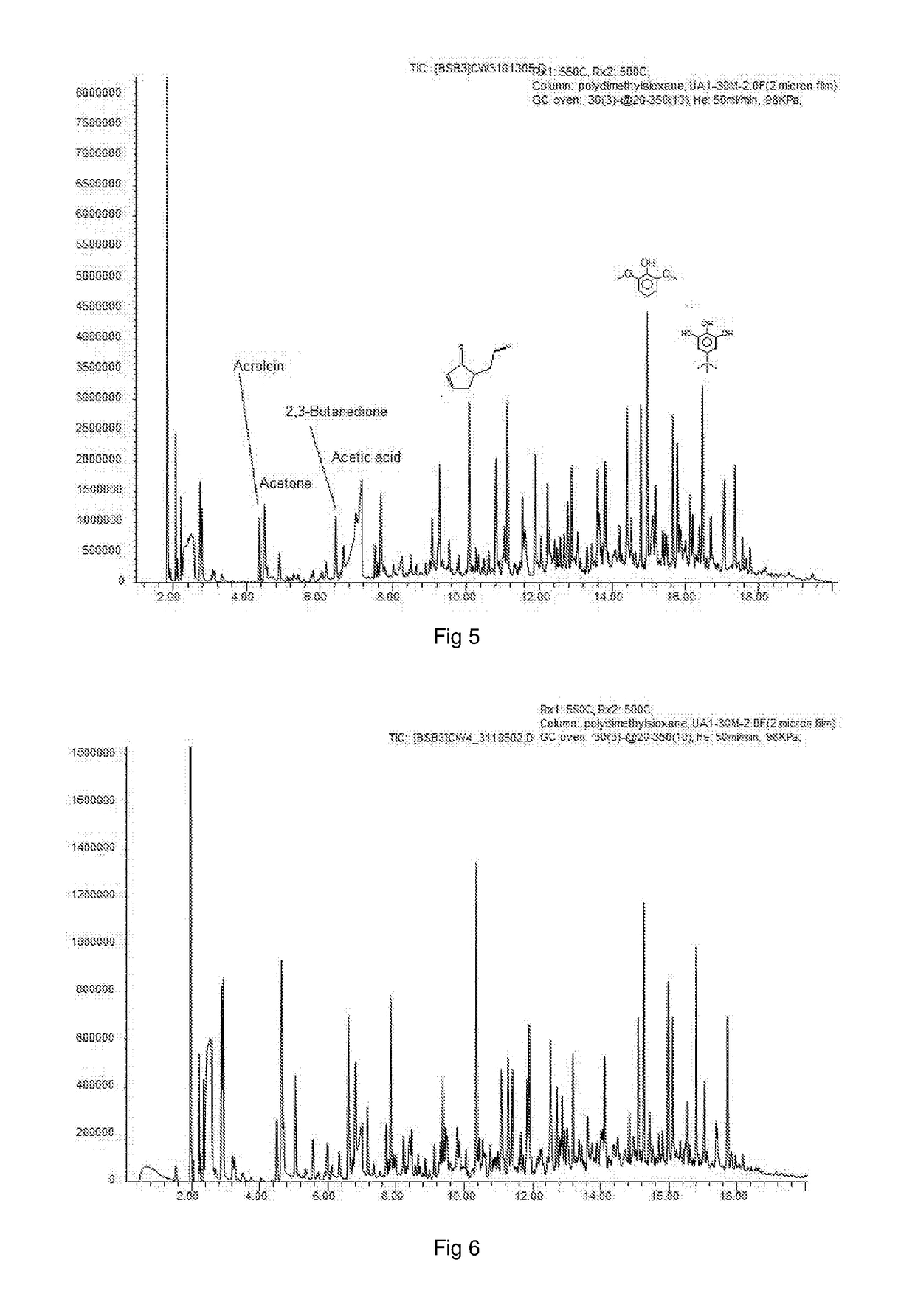
[0059]FIG. 5 shows the composition analysis results of the pyrolysis oil deoxygenation for a Ca—Al LDH looping catalyst system;

[0060]FIG. 6 shows the composition results of the pyrolysis oil produced without a deoxygenation catalyst system of the invention;

[0061]FIG. 7 shows the composition analysis results of the pyrolysis oil deoxygenation for a Mg—Al LDH looping catalyst system;

[0062]FIG. 8 shows the composition results...


PUM

PropertyMeasurementUnit
temperatureaaaaaaaaaa
temperaturesaaaaaaaaaa

Abstract

The invention provides a catalyst system and method for the deoxygenation of hydrocarbons, such as bio-oil, using a sulphide-sulfate or an oxide-carbonate (LDH) system. The invention extends to a pyrolysis process of a carbonaceous bio-mass wherein a first combustion zone is carried out in one or more combustion fluidised beds in which a particulate material including chemically looping deoxygenation catalyst particles is fluidised and heated, and a second pyrolysis zone carried out in one or more pyrolysis fluidised beds in which the hot particles, including the catalyst particles, heated in the combustion zone are used for pyrolysis of the bio-mass, said combustion zone being operated at a temperature of from 250° C. to 1100° C., typically around 900° C., and the pyrolysis zone being operated at a temperature of from 250° C. to 900° C., typically 450° C. to 600° C., said catalyst particles being oxygenated in the pyrolysis zone in the presence of oxygenates in the pyrolysis oil and regenerated in the combustion zone either by calcining to drive off the carbon oxides, such as CO2, or by reduction to its form which is active for deoxygenation of the pyrolysis oil.

Description

FIELD OF THE INVENTION[0001]The invention relates to a catalyst for reduction of oxygenates, a use for such a catalyst, and processes using said catalyst. One such type of process is reduction of oxygenates in bio-oils produced from carbonaceous material of plant origin.BACKGROUND TO THE INVENTION[0002]Sourcing secondary materials from wood such as pulp, dissolving pulp, or lignin involves the thermochemical degradation through the use of moderate temperatures and chemicals readily reactive with wood. Research into developing other materials from wood such as fuel oils and chemicals has made use of similar thermochemical processes albeit at harsher conditions. The degree to which wood is thermally and / or chemically degraded will determine the type of products obtained. Subjecting wood to moderately high temperatures of between 400° C.-500° C. using fast heating rates produces a fuel rich in valuable chemicals called pyrolysis oil.[0003]Pyrolysis oil is difficult to process into more...

Claims


Application Information

Patent Timeline
Patent Type & Authority Applications(United States)
IPC IPC(8): B01J27/04B01J21/20B01J21/16B01J27/30B01J38/02C10G3/00C10G1/08
CPCB01J27/04B01J21/20B01J21/16B01J27/30B01J38/02C10G3/57C10G3/40C10G1/086C10G2300/1011C10G1/10C10G3/45C10G3/49C10G2300/1014Y02P30/20Y02E50/10
Inventor HEYDENRYCH, MICHAELDEL FABBRO, OLINTOFOCKE, WALTERLABUSCHAGNE, FREDERICKMERCKEL, RYAN
Owner UNIVERSITY OF PRETORIA
Learn More