
A catalytic process for reducing chloride content of a hydrocarbon feed stream

a technology of hydrocarbon feed stream and catalytic process, which is applied in the direction of hydrocarbon oil treatment, liquid hydrocarbon mixture production, refining to eliminate heteroatoms, etc., can solve problems such as equipment corrosion

Inactive Publication Date: 2019-02-28
SABIC GLOBAL TECH BV
View PDF1 Cites 4 Cited by
  • Summary
  • Abstract
  • Description
  • Claims
  • Application Information

AI Technical Summary

Benefits of technology

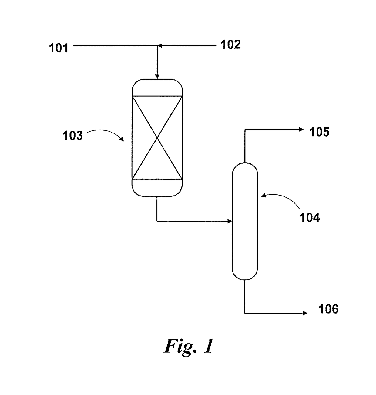
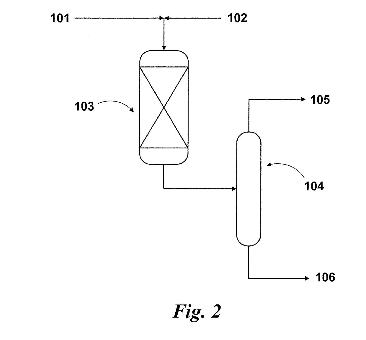
The present disclosure relates to a process for reducing the chloride content of a hydrocarbon feed stream. The process involves contacting the hydrocarbon feed stream with a sulfided catalyst or a catalyst containing at least one of Pd, Pt, Cu, and Zn on a catalyst support in the presence of hydrogen gas at a temperature of 60-200° C and a pressure of 25-35 barg. The process results in the reduction of organic chloride compounds in the hydrocarbon feed stream and the formation of a hydrocarbon product stream with lower chloride content. The process can be carried out at a high temperature and pressure using a sulfided catalyst and a hydrogen gas to crack the chloride containing pyrolysis oil and reduce the chloride content of the hydrocarbon feed stream. The process can also involve removing the HCl from the hydrocarbon product stream through stripping, washing, and neutralizing. Overall, the process provides a simple and effective way to reduce the chloride content of hydrocarbon feeds.

Problems solved by technology

However, plastic waste may contain polyvinylchloride (PVC) which leads to the formation organic chlorides during the pyrolysis process.
The organic chlorides may then form HCl in downstream processes, which can cause corrosion of equipment and may also act as a poison for catalysts used in the downstream processes.

Method used


Image

  • A catalytic process for reducing chloride content of a hydrocarbon feed stream
  • A catalytic process for reducing chloride content of a hydrocarbon feed stream
  • A catalytic process for reducing chloride content of a hydrocarbon feed stream

Examples


example 1

[0072]Referring to FIG. 3:

[0073]Catalyst loading: 0.6426 g NiMo catalyst

[0074]Catalyst pretreatment—Sulfided (Sulfided using 3 wt. % S (DMDS) in hexadecane up to 345° C. after reduction with hydrogen up to 180° C.

[0075]Feed (as described above) 4000 ppmw Cl and 3 wt. S in the form of DMDS

[0076]Feed rate 1.27 g / h

[0077]H2 / HC ratio equals 1 (all the hydrocarbon feed including chloride species)

[0078]Temperature=300° C., Reactor Inlet Pressure=30 barg.

[0079]As can be seen from FIG. 3, all of the different types of chlorinated species are converted at a temperature of 300° C. using the NiMo catalyst.

example 2

[0080]Referring to FIG. 4:

[0081]Catalyst loading: 0.6426 g NiMo catalyst

[0082]Catalyst pretreatment—Sulfided (Sulfided using 3 wt. % S (DMDS) in hexadecane up to 345° C. after reduction with hydrogen up to 180° C.

[0083]Feed (as described above) 4000 ppmw Cl and 3 wt. S in the form of DMDS

[0084]Feed rate 1.27 g / h

[0085]H2 / HC molar ratio=1 (including n-hexadecane and chloride species)

[0086]Temperature=200° C., Reactor Inlet Pressure=30 barg.

[0087]As can be seen from FIG. 4, all of the aliphatic chlorinated species are converted at a temperature of 200° C. using the NiMo catalyst, while the aromatic chloride species are not.

example 3

[0088]Referring to FIG. 5:

[0089]Catalyst loading: 0.6417 g Pd catalyst

[0090]Catalyst pretreatment—Catalyst reduced in hydrogen at 400° C.

[0091]Feed (as described above) 4000 ppmw Cl

[0092]Feed rate=1.28 g / h

[0093]H2 / HC molar ratio=1 (including n-hexadecane and chloride species)

[0094]Temperature=200° C., Reactor Inlet Pressure=30 barg.

[0095]As can be seen from FIG. 5, all of the different types of chlorinated species are converted at a temperature of 200° C. using the Pd / Al2O3 catalyst. This result is advantageous in that all aromatic chloride species are also converted at low temperature (200° C.).


PUM

PropertyMeasurementUnit
temperatureaaaaaaaaaa
boiling pointaaaaaaaaaa

Abstract

A process for reducing a chloride content of a hydrocarbon feed stream involving contacting a hydrocarbon feed stream comprising a chloride containing pyrolysis oil obtained by cracking a chloride containing thermoplastic material with a sulfided catalyst comprising at least one of Co, Mo, and Ni or a catalyst comprising Pd, Pt, Cu, and / or Zn on a catalyst support in the presence of hydrogen gas to reduce one or more organic chloride compounds present in the hydrocarbon feed stream and form a hydrocarbon product stream and HCl. The HCl is removed from the hydrocarbon product stream, wherein the hydrocarbon product stream has a lower chloride content than the hydrocarbon feed stream based on the total weight of the chloride and the total weight of the hydrocarbon feed stream.

Description

BACKGROUND OF THE INVENTIONTechnical Field[0001]The present invention relates to a process of reducing the chloride content of a hydrocarbon feed stream comprising a chloride containing pyrolysis oil by contacting the hydrocarbon feed stream with a catalyst in the presence of hydrogen gas.Description of the Related Art[0002]The “background” description provided herein is for the purpose of generally presenting the context of the disclosure. Work of the presently named inventors, to the extent it is described in this background section, as well as aspects of the description which may not otherwise qualify as prior art at the time of filing, are neither expressly or impliedly admitted as prior art against the present invention.[0003]Plastic waste may be converted into useful liquids, gas fuels or commodity chemicals using a pyrolysis process. However, plastic waste may contain polyvinylchloride (PVC) which leads to the formation organic chlorides during the pyrolysis process. The orga...

Claims


Application Information

Patent Timeline
Patent Type & Authority Applications(United States)
IPC IPC(8): C10G45/08C10G45/10C10G45/04C10G67/10
CPCC10G45/08C10G45/10C10G45/04C10G67/10C10G2300/201C10G45/06C10G1/10
Inventor HAKEEM, ABRAR A.GHOSH, ASHIM KUMAR
Owner SABIC GLOBAL TECH BV
Learn More