
Tire

a technology of tires and wheels, applied in the field of tires, can solve the problems of deterioration of steering stability on dry road surfaces, and achieve the effect of securing steering stability and excellent wet performance over a long period of tim

Active Publication Date: 2019-02-28
SUMITOMO RUBBER IND LTD
View PDF0 Cites 2 Cited by
  • Summary
  • Abstract
  • Description
  • Claims
  • Application Information

AI Technical Summary

Benefits of technology

The present invention aims to address the problems of tires in terms of their wet performance and steering stability. The technical effect of this patent text is to provide a tire that can perform well in wet conditions for a longer period of time while maintaining steering stability.

Problems solved by technology

Thereby, steering stability tends to deteriorate on a dry road surface for the tires mentioned above.

Method used


Image

  • Tire
  • Tire
  • Tire

Examples


working example (example)

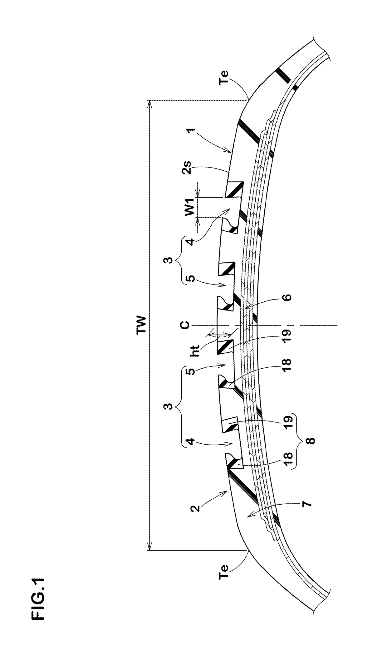
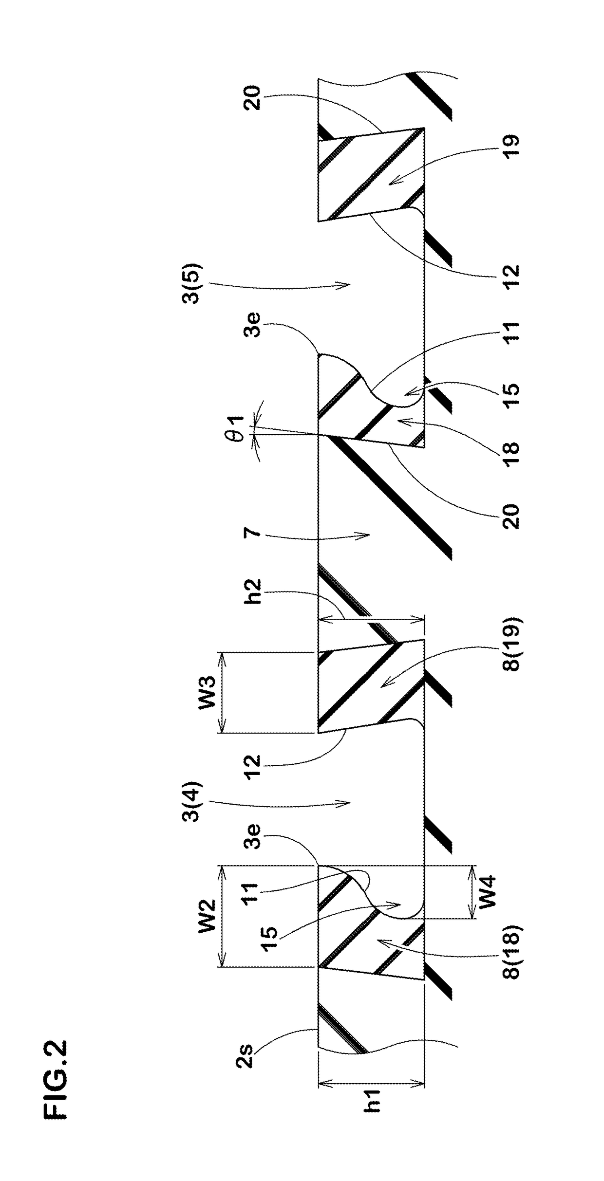
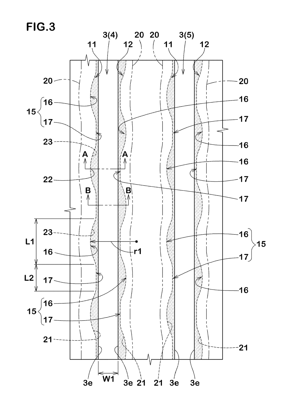
[0072]Tires of size 245 / 45R19 having the main grooves described above were made by way of test according to the specifications listed in Table 1. As References 1 and 2, tires having the groove wall rubber having the same complex elastic modulus as that of the base rubber were made by way of test. As shown in FIGS. 6A and 6B, each of main grooves (a) of the tire as the Reference 1 is provided on the groove walls on both sides respectively thereof with recessed portions (b) each having the constant recess mount in the tire circumferential direction. Note that the groove volume of each of the main grooves (a) of the Reference 1 is the same as the groove volume of each of the main grooves of Example 1. The tire as the Reference 2 has the main grooves each having the shape shown in FIG. 3. Each of the test tires was tested for the steering stability, the ride comfort, and the wet performance after the tire is worn. Common specifications of the test tires and the test methods are as follo...


PUM


Abstract

A tire comprises a tread portion 2. The tread portion 2 includes a tread ground contacting surface (2s) and at least one main groove 3 recessed from the tread ground contacting surface (2s) and extending continuously in a tire circumferential direction. The main groove 3 has a first groove wall 11. The first groove wall is provided with a recessed portion 15 recessed outwardly in a groove width direction from a groove edge of the main groove 3 on the tread ground contacting surface. The recessed portion 15 is formed of groove wall rubber 8 having a complex elastic modulus larger than that of base rubber 7 forming a main portion of the tread ground contacting surface (2s).

Description

TECHNICAL FIELD[0001]The present invention relates to a tire having a tread portion provided with a main groove.BACKGROUND ART[0002]For example, Japanese Unexamined Patent Application Publication No. H05-338412 has disclosed a tire in which a tread portion is provided with main grooves. Each of the main grooves mentioned above has groove wall surfaces extending obliquely in a direction so that a groove width thereof decreases from a groove bottom surface thereof to a tread surface thereof. The main grooves configured as such are advantageous for maintaining a drainage property after the tread portion is worn.[0003]However, groove edge side portions of land regions divided by the main grooves tend to collapse toward a groove center of respective one of the main grooves with a connecting portion between each of the groove walls and respective one of the groove bottom surfaces as a fulcrum during running. Thereby, steering stability tends to deteriorate on a dry road surface for the ti...

Claims


Application Information

Patent Timeline
Patent Type & Authority Applications(United States)
IPC IPC(8): B60C11/13B60C11/00
CPCB60C11/1315B60C11/005B60C11/1323B60C2200/06B60C11/042B60C11/0066B60C11/0058B60C11/0041B60C11/1236B60C11/045B60C2011/133B60C11/1346
Inventor KAJITA, HIROAKI
Owner SUMITOMO RUBBER IND LTD
Learn More