
Pneumatic tire

A technology of pneumatic tires and tires, applied in tire parts, tire tread/tread pattern, transportation and packaging, etc., to improve wet performance and handling stability, improve rigidity, and prevent shear deformation.

Active Publication Date: 2018-03-20
SUMITOMO RUBBER IND LTD
View PDF12 Cites 7 Cited by
  • Summary
  • Abstract
  • Description
  • Claims
  • Application Information

AI Technical Summary

Problems solved by technology

However, with the pneumatic tire of Patent Document 1, there is still room to improve wet performance and steering stability

Method used


Image

  • Pneumatic tire
  • Pneumatic tire
  • Pneumatic tire

Examples


Embodiment Construction

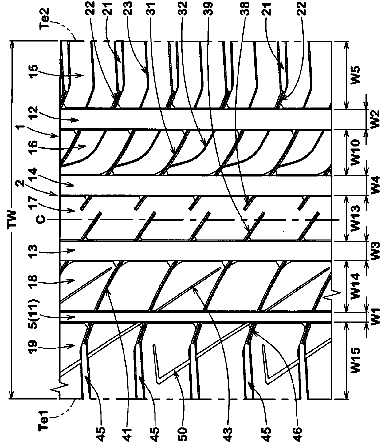
[0029] Hereinafter, an embodiment of the present invention will be described with reference to the drawings. figure 1 It is a developed view showing a tread portion 2 of a pneumatic tire (hereinafter also simply referred to as a "tire") 1 according to an embodiment of the present invention. The tire 1 of the present embodiment is applicable to, for example, passenger vehicles.

[0030] Such as figure 1 As shown, the tread portion 2 has an asymmetrical tread pattern specifying an installation orientation on a vehicle. The tread portion 2 has a first tread end Te1 positioned outside the vehicle when the tire 1 is mounted on the vehicle, and a second tread end Te2 positioned inside the vehicle when mounted on the vehicle. For example, a character or a symbol is attached to a side wall portion (not shown) to indicate an installation orientation on a vehicle.

[0031] Each of the tread ends Te1 and Te2 is the outermost contact position in the tire axial direction when a normal l...


PUM


Abstract

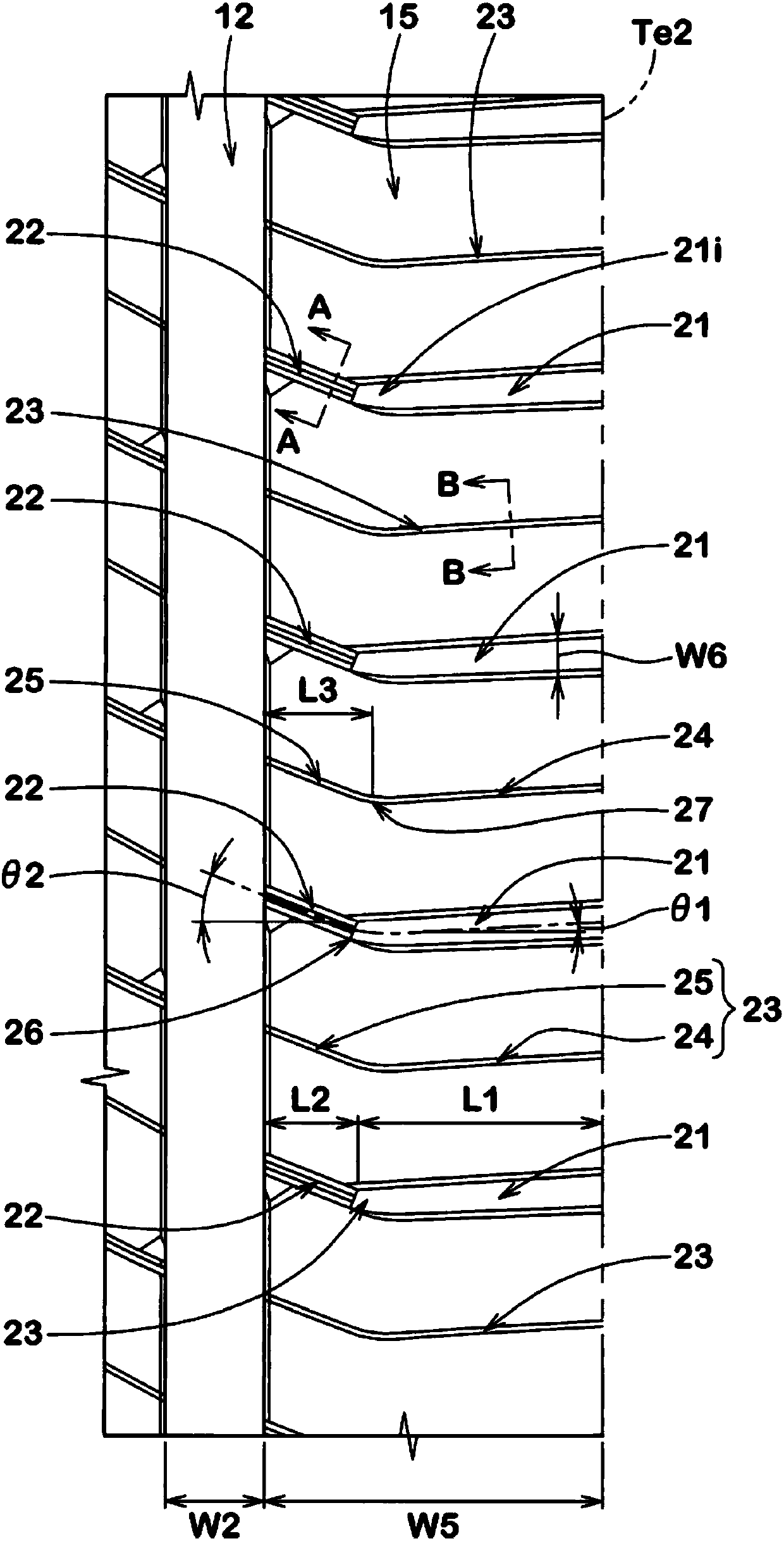
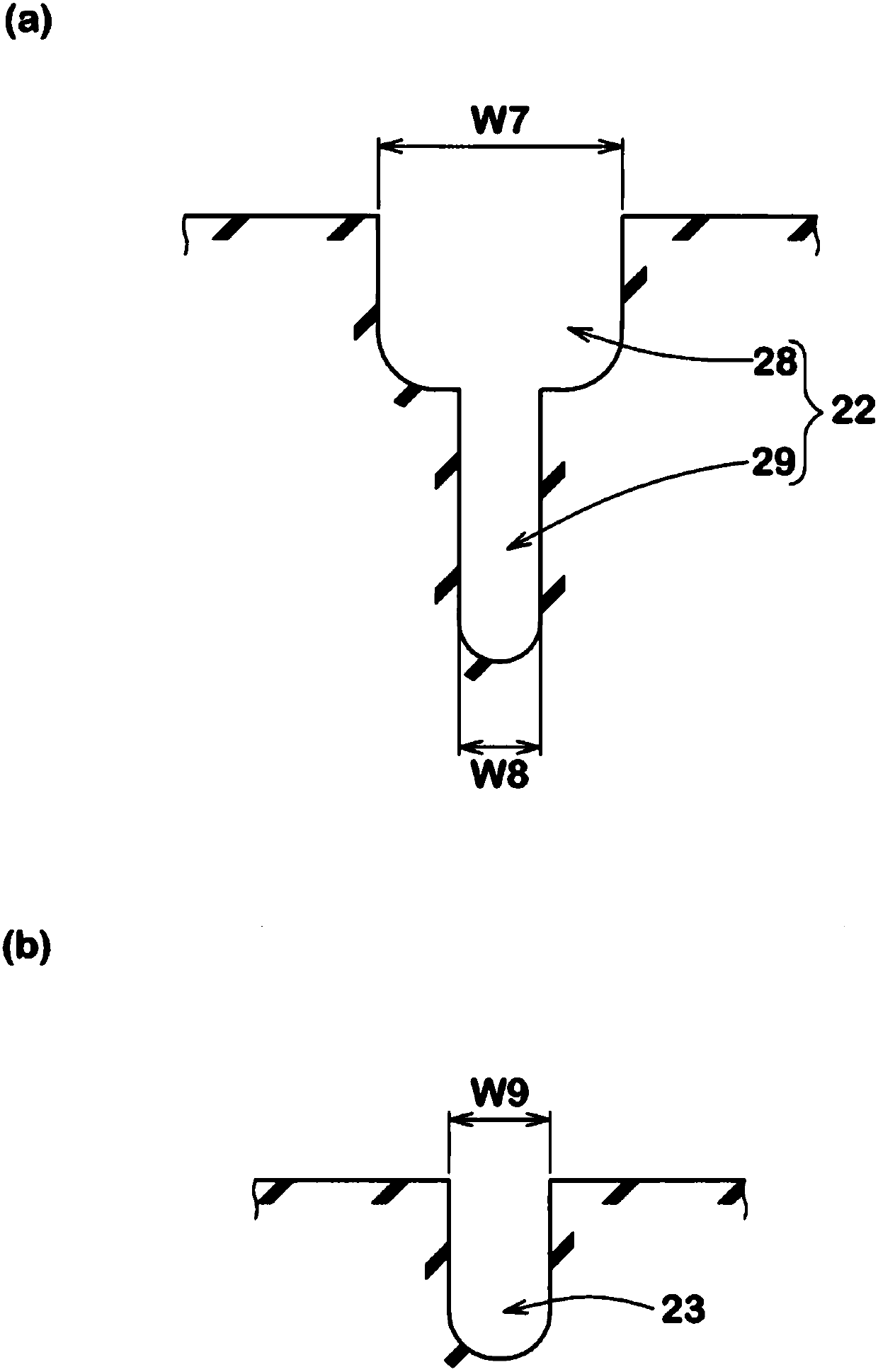
The invention aims to provide a pneumatic tire, which has excellent wetland properties and operation stability. A pneumatic tire 1 comprises a tread portion 2 having an outboard tread edge Te1 to be positioned away from the center of a vehicle body and an inboard tread edge Te2 to be positioned close to the center of the vehicle body. The tread portion 2 is provided with an inboard shoulder main groove 12, and an inboard shoulder land region 15 between the inboard shoulder main groove 12 and the inboard tread edge Te2. The inboard shoulder land region 15 is provided with inboard shoulder rug grooves 21, connecting sipes 22, and inboard shoulder sipes 23. The inboard shoulder sipe 23 is made up of a straight outer part 24 extending from the inboard tread edge Te2 toward the axially inside,and a straight inner part 25 extending to the inboard shoulder main groove 12 at a flexion angle with respect to the outer part 24. The axial length of the inner part 25 is more than the axial lengthof the connecting sipe 22.

Description

technical field [0001] The present invention relates to a pneumatic tire having excellent wet performance and handling stability. Background technique [0002] For example, Patent Document 1 below proposes a pneumatic tire provided with a plurality of shoulder lateral grooves with a small groove width and a gap between them in order to maintain the rigidity of the inner shoulder land portion and improve wet performance. sipes. However, with the pneumatic tire of Patent Document 1, there is room to improve wet performance and steering stability. [0003] [Prior Art Literature] [0004] 【Patent Literature】 [0005] [Patent Document 1] Japanese Patent Laid-Open No. 2012-218650 Contents of the invention [0006] The present invention has been made in view of the above problems, and an object of the present invention is to provide a pneumatic tire capable of exhibiting excellent wet performance and steering stability. [0007] [Means to solve technical problems] [0008] ...

Claims


Application Information

Patent Timeline
Patent Type & Authority Applications(China)
IPC IPC(8): B60C11/03B60C11/12B60C11/13
CPCB60C11/03B60C11/1281B60C11/1307B60C2011/0339B60C11/1218B60C11/1236B60C2011/0388B60C11/0304B60C11/1204
Inventor 若杉将史
Owner SUMITOMO RUBBER IND LTD
Learn More