
Meta projector and electronic apparatus including the same

a technology of electronic equipment and projectors, applied in the field of metal projectors and electronic equipment, can solve the problems of affecting design precision and fabrication conditions, the volume occupied by such optical components,

Active Publication Date: 2019-02-21
SAMSUNG ELECTRONICS CO LTD
View PDF9 Cites 9 Cited by
  • Summary
  • Abstract
  • Description
  • Claims
  • Application Information

AI Technical Summary

Benefits of technology

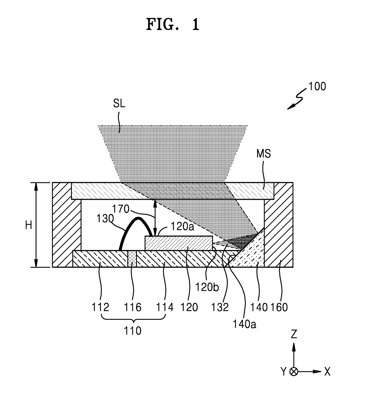
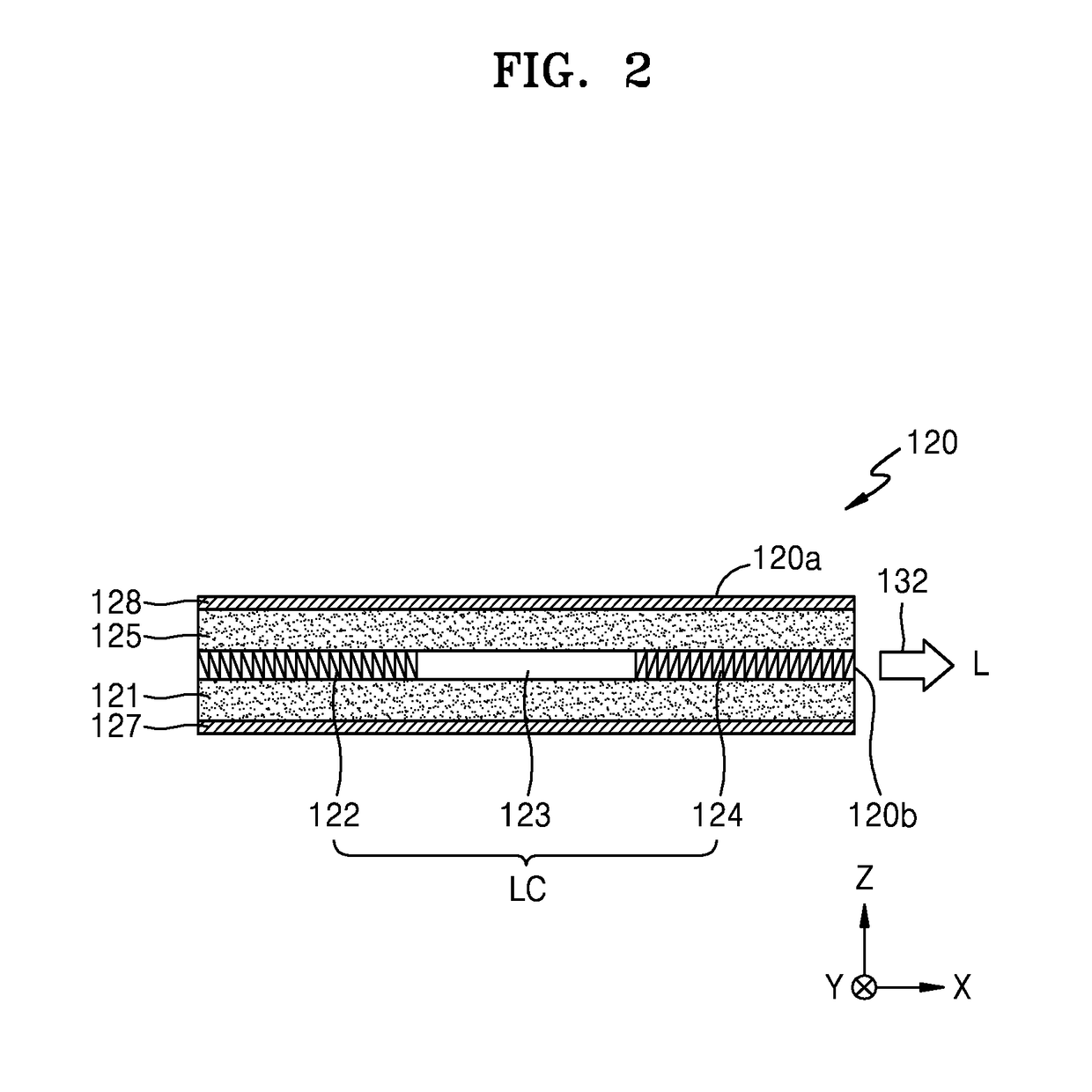
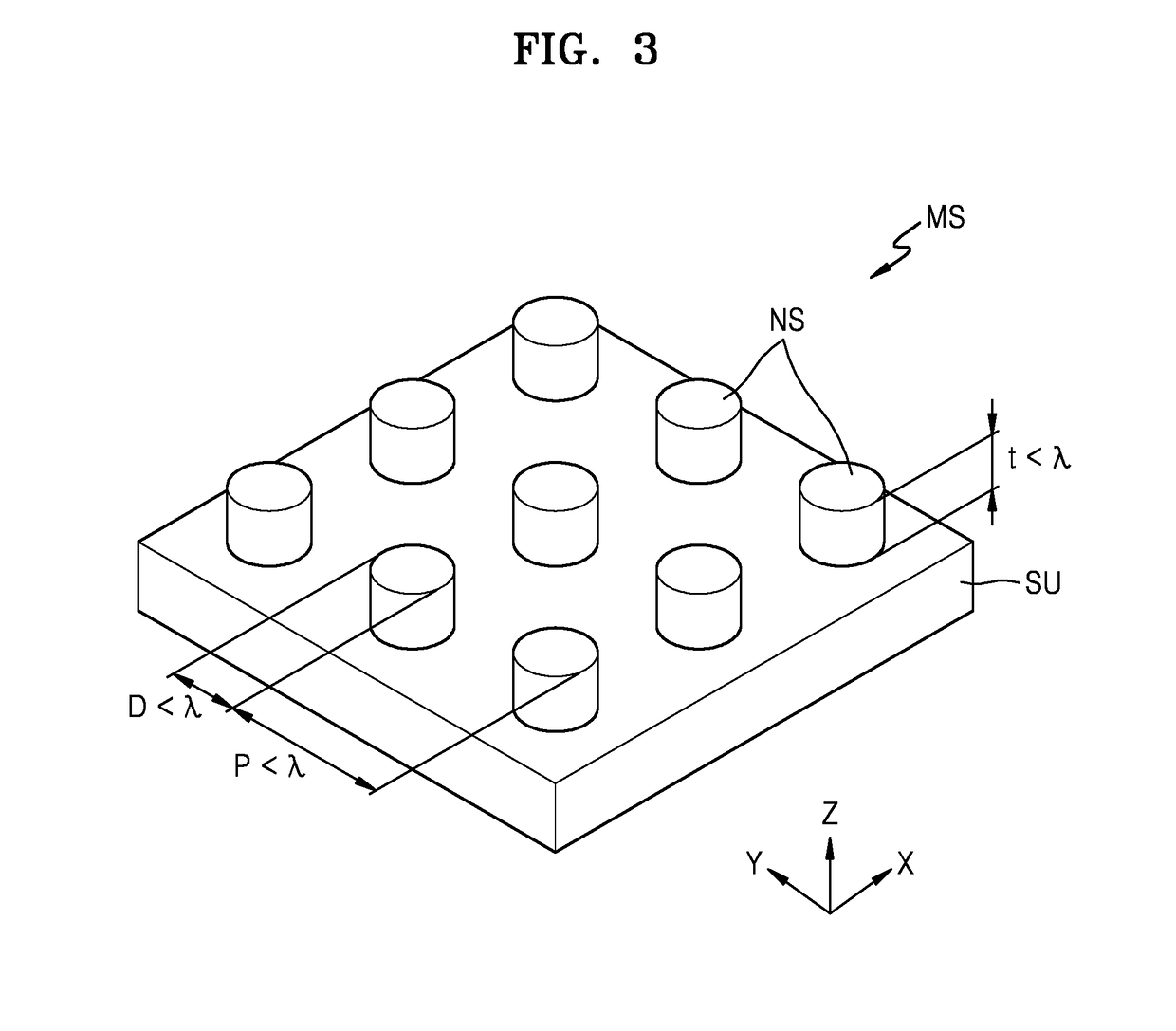
The patent describes a meta projector that can output light with a desired performance, such as structured light with a specific pattern. The meta projector includes a substrate, an edge emitting device, and a path changing member. The edge emitting device emits light through its side surface and the path changing member changes the path of the light emitted from the edge emitting device. The meta-projector may also include a housing and a meta-structure layer with nanostructures arranged in a regular or random distribution to deflect and output the structured light in a particular direction. The nanostructures may have a higher refractive index than the surrounding material and may be conductive or arranged with an asymmetry shape distribution. The plurality of nanostructures may be arranged with a pitch of one-half of the wavelength of the light emitted from the edge emitting device. The path changing member may include a reflective surface with nanostructures arranged to adjust a divergence angle of incident light. The meta-projector may be used in electronic apparatuses and depth recognition apparatuses.

Problems solved by technology

The volume occupied by such optical components is a factor affecting design precision and fabrication conditions.

Method used


Image

  • Meta projector and electronic apparatus including the same
  • Meta projector and electronic apparatus including the same
  • Meta projector and electronic apparatus including the same

Examples


Embodiment Construction

[0073]Reference will now be made in detail to example embodiments, at least some of which are illustrated in the accompanying drawings, wherein like reference numerals refer to like elements throughout. In this regard, some example embodiments may have different forms and should not be construed as being limited to the descriptions set forth herein. Accordingly, the example embodiments are merely described below, by referring to the figures, to explain aspects. As used herein, the term “and / or” includes any and all combinations of one or more of the associated listed items. Expressions such as “at least one of,” when preceding a list of elements, modify the entire list of elements and do not modify the individual elements of the list.

[0074]Hereinafter, example embodiments of the present disclosure will be described with reference to the accompanying drawings. In the drawings, like reference numbers refer to like elements, and the sizes of elements may be exaggerated for clarity of i...


PUM


Abstract

A meta projector is provided, including an edge emitting device configured to emit light through a side surface thereof, a meta-structure layer spaced apart from the upper surface of the edge emitting device that includes a plurality of nanostructures having a sub-wavelength dimension smaller than a wavelength of the light emitted from the edge emitting device, and a path changing member configured to change a path of the light emitted from the edge emitting device so as to direct the path toward the meta-structure layer. The meta projector may thus be configured to emit a light pattern of structured light, based on directing the light emitted from the edge emitting device through the meta-structure layer.

Description

CROSS-REFERENCE TO RELATED APPLICATION[0001]This is a Continuation-In-Part Application of U.S. application Ser. No. 15 / 991,005 filed on May 29, 2018, which claims priority under 35 U.S.C. § 119, of Korean Patent Application No. 10-2017-0097134, filed on Jul. 31, 2017, in the Korean Intellectual Property Office, the disclosures of which are incorporated herein in their entirety by reference.BACKGROUND1. Field[0002]Example embodiments relate to a meta projector and an electronic apparatus including the meta projector.2. Description of the Related Art[0003]Recently, demand has gradually increased for small laser projectors for combination with any of various electronic apparatuses.[0004]For example, ultra-small projectors may be used for augmented reality (AR), virtual reality (VR), and mixed reality (MR) implemented by mobile and wearable devices, and laser projectors may be used to form structured light in depth sensors used to accurately recognize three-dimensional shapes of objects...

Claims


Application Information

Patent Timeline
IPC IPC(8): G06T7/521G06T7/73G06T7/55G06T7/514H04N5/247H01S5/00H01S5/022G06F1/16
CPCG06T7/521G06T7/74G06T7/55G06T7/514H04N5/247H01S5/0071H01S5/02296G06F1/1673G06T2207/10028G06T2207/20224G06T2207/10048H01S5/02216G02B1/118G02B5/1809G06F1/1639H04N13/239H04N13/254H04N13/128H04N13/122H04N2013/0081G01B11/2513G06F3/0304G06F3/04886H01S5/02345H01S5/02257H01S5/02253G01B11/2545H04N23/90
Inventor HAN, SEUNGHOONNA, BYUNGHOONYOU, JANGWOO
Owner SAMSUNG ELECTRONICS CO LTD
Learn More