
Wireless power receiver and transfer, wireless power transceiver system, and wireless power transceiver mobile device

a wireless power transceiver and wireless power technology, applied in the direction of receivers, inductances, near-field systems, etc., can solve the problems of inability to wireless energy transfer, the energy transfer efficiency deteriorates rapidly, and the battery life is extremely dominant, so as to improve the q factor of wireless power transceivers, secure the wireless power transfer efficiency, and reinforce the electric field or magnetic field

Inactive Publication Date: 2017-06-13
FOUND OF SOONGSIL UNIV IND COOP
View PDF11 Cites 1 Cited by
  • Summary
  • Abstract
  • Description
  • Claims
  • Application Information

AI Technical Summary

Benefits of technology

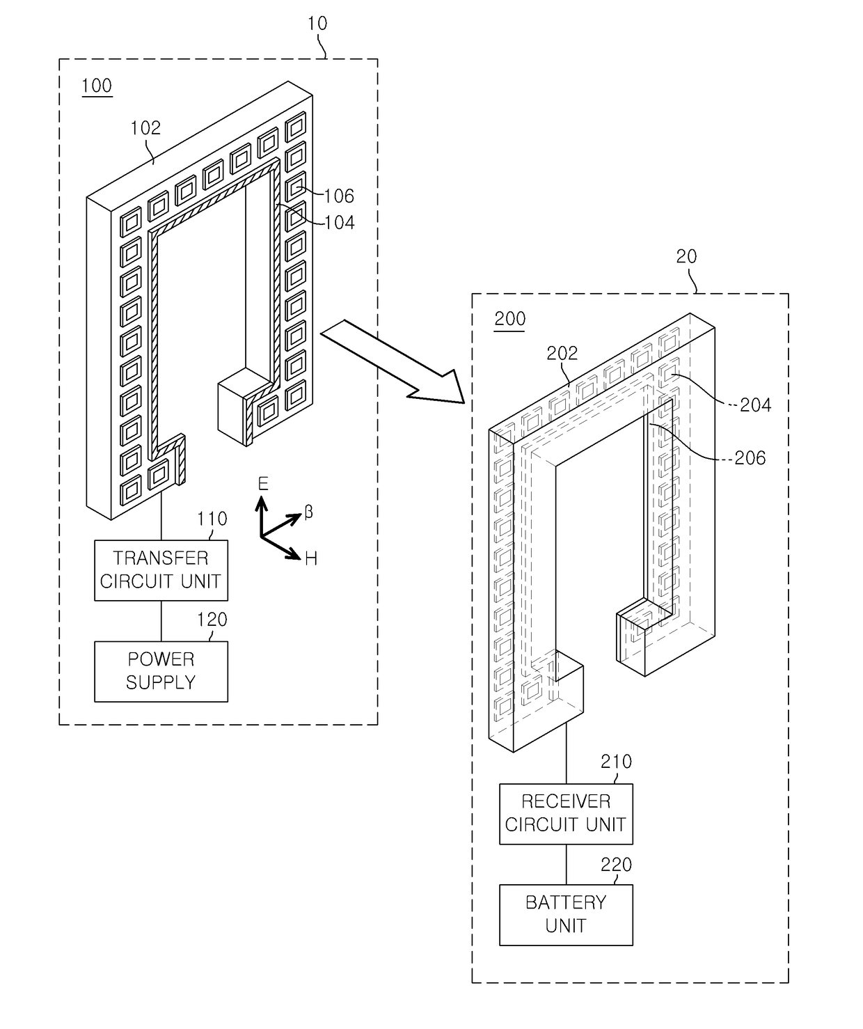
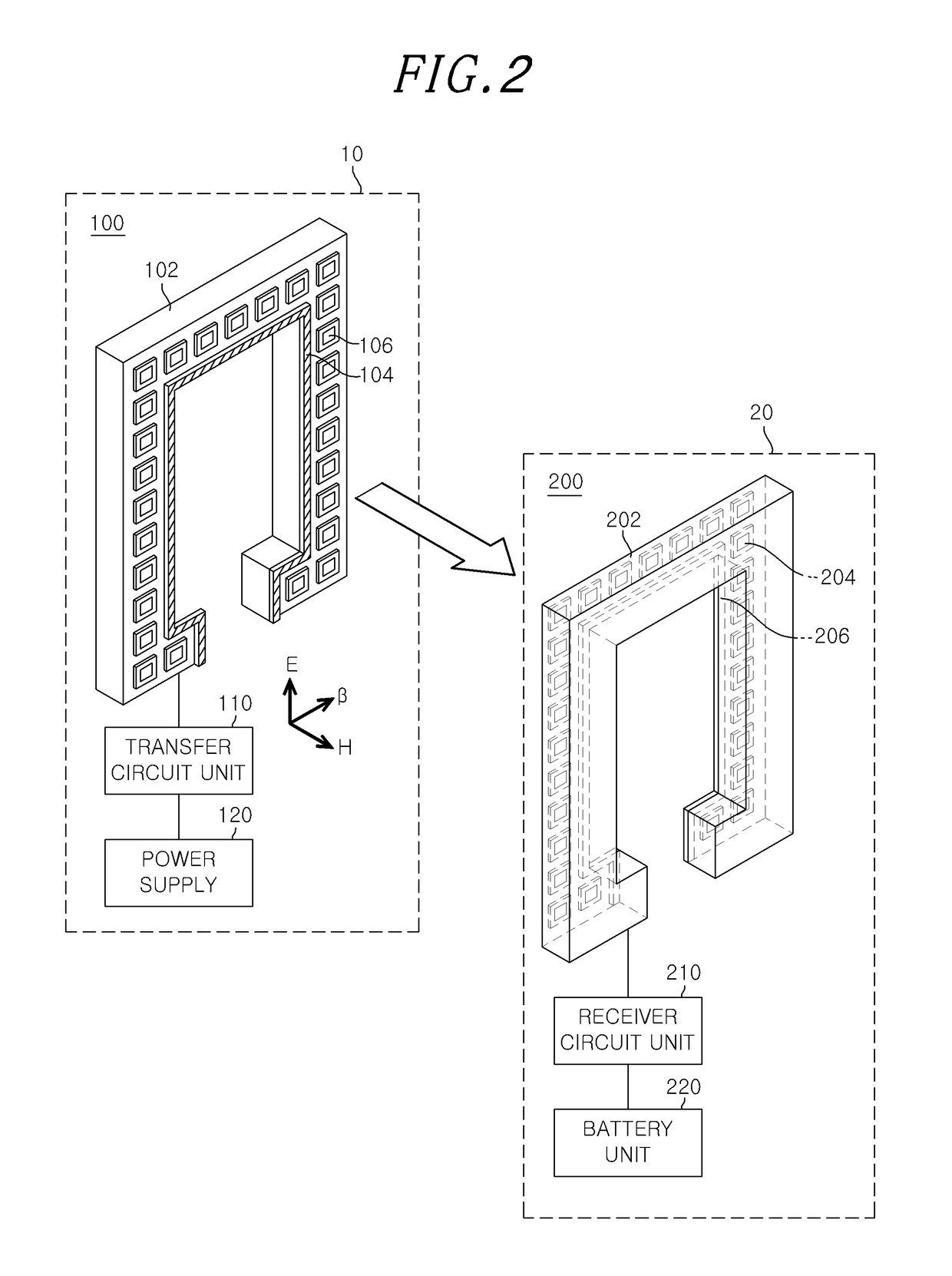
[0015]In view of the above, the present invention provides a wireless power transceiver technique capable of improving the Q factor of a wireless power transceiver to reinforce electric fields or magnetic fields, for example, amplify or focus the fields.
[0016]Further, the present invention provides a wireless power transceiver technique capable of securing wireless power transfer efficiency of at least 80% in a specific radio frequency band, for example, a 13.56 MHz frequency band used for an NFC (Near Field Communication) technique.
[0038]As mentioned above, in accordance with an embodiment of the present invention, it is possible to reinforce the electric fields or magnetic fields through the improvement of the Q factor of the wireless power transceiver and secure the wireless power transfer efficiency of at least 80% in a 13.56 MHz frequency band used for the NFC. In addition, it is also possible to reduce the size of the wireless power transceiver mobile device while securing enough the wireless power transfer efficiency.

Problems solved by technology

However, the systems applied to these application fields have a capability of performing wireless communications, but they have still manifested the problem in terms of the energy supply and transfer.
In addition, these systems have an extremely dominant problem in the life of the battery and fuel, an amount of energy that can be transferred in a wireless manner.
However, the inductance coupling technique by electromagnetic waves has a drawback that energy transfer efficiency deteriorates rapidly if the coupling coefficient of inductors is not high and hence wireless energy transfer is not possible when leaving a specific location.
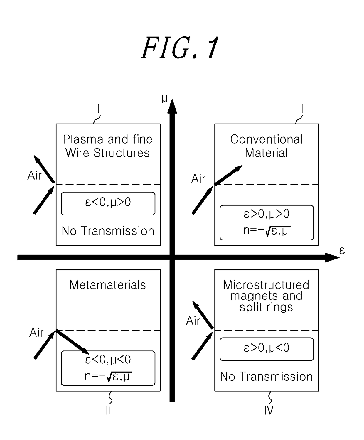
Of course, there exist some technologies in which the wireless power transfer technology is adopted to meta-materials, but it is hard for these technologies to enhance sufficiently the fields of electric and magnetic fields by raising the resonance characteristics of the wireless power resonator.

Method used


Image

  • Wireless power receiver and transfer, wireless power transceiver system, and wireless power transceiver mobile device
  • Wireless power receiver and transfer, wireless power transceiver system, and wireless power transceiver mobile device
  • Wireless power receiver and transfer, wireless power transceiver system, and wireless power transceiver mobile device

Examples


Embodiment Construction

[0052]The advantages and features of exemplary embodiments of the present invention and methods of accomplishing them will be clearly understood from the following description of the embodiments taken in conjunction with the accompanying drawings. However, the present invention is not limited to those embodiments and may be implemented in various forms. It should be noted that the embodiments are provided to make a full disclosure and also to allow those skilled in the art to know the full scope of the present invention. Therefore, the present invention will be defined only by the scope of the appended claims.

[0053]In the following description, well-known functions or constitutions will not be described in detail if they would unnecessarily obscure the embodiments of the invention. Further, the terminologies to be described below are defined in consideration of functions in the invention and may vary depending on a user's or operator's intention or practice. Accordingly, the definit...


PUM

PropertyMeasurementUnit
dielectric constantaaaaaaaaaa

Abstract

A wireless power receiver includes a receiver resonator configured to be coupled to a source resonator to receive a power from the source resonator, the receiver resonator comprising: an inverted U-shaped dielectric layer whose distal ends are bent inward; an antenna patterned in the form of a loop in line with the shape of the dielectric layer; and a meta-structure arranged around the antenna on the dielectric layer, wherein the meta-structure is configured to reinforce at least one of the electric fields and magnetic fields that are formed in the receiver resonator.

Description

RELATED APPLICATIONS[0001]This application claims the benefit of Korean Patent Application No. 10-2012-0097330, filed on Sep. 3, 2012, which is hereby incorporated by reference as if fully set forth herein.FIELD OF THE INVENTION[0002]The present invention relates to a wireless power transceiver technology, and, more particularly, to a wireless power receiver and transfer, wireless power transceiver system, and wireless power mobile device adapted to raise wireless power transceiver efficiency.BACKGROUND OF THE INVENTION[0003]The rapid development of wireless communication technologies enables a new challenge to the application fields looked possible in virtual reality, and hence many of the application fields have been implemented and realized immediately accordingly.[0004]Among others, most notable fields are U-City using USN (Ubiquitous Sensor Network), Femtocells that enable home networks, Robots that play the role of home helpers, unmanned aircraft that carry out emergency missi...

Claims


Application Information

Patent Timeline
Patent Type & Authority Patents(United States)
IPC IPC(8): H01F27/42H01F37/00H01F38/00H01Q15/00H04B5/02H01Q7/00H04B5/00G02F1/23G02F1/00
CPCH01Q7/005G02F1/00G02F1/23H01Q7/00H01Q15/0086H04B5/0037H04B5/0081H04B5/02H02J50/12
Inventor SEO, CHUL HUNLEE, CHONGMIN
Owner FOUND OF SOONGSIL UNIV IND COOP
Learn More