
Control system and method for additive manufacturing

a technology of control system and additive manufacturing, which is applied in the direction of additive manufacturing process, manufacturing tool, manufacturing enclosure, etc., can solve the problems of not being able to clearly define and/or understand the effects of the mentioned manufacturing conditions on the quality or performance of the base material, such as the powder, and it is generally very difficult to track the quality and manage the movement of parts of the base material. , to achieve the effect of facilitating management and/or handling of the base material and facilitating the overview

Active Publication Date: 2019-02-21
SIEMENS ENERGY GLOBAL GMBH & CO KG
View PDF2 Cites 1 Cited by
  • Summary
  • Abstract
  • Description
  • Claims
  • Application Information

AI Technical Summary

Benefits of technology

The invention relates to a control system for managing and tracking the quality of base material used in additive manufacturing, which involves keeping a record of the location and quality of the material as it moves through different manufacturing processes. This system uses containers to retain the base material, and a tracking system to keep up-to-date on the quality of each container and its contents. The control system can be easily adapted by operators and helps in ensuring consistent quality across different manufacturing jobs. The system also allows for easier handling and disposal of the base material. Overall, the invention provides better quality control and management of the base material, making it easier to manufacture components with high quality.

Problems solved by technology

This makes it generally very difficult to track the quality and manage the movement of portions of base material, which may be present in numerous containers, manufacturing systems or powder buckets of the system.
Currently the effects of the mentioned manufacturing conditions on the quality or performance of the base material, such as the powder, are not very well defined and or understood, as the quality of e.g. the powder depends on various different aspects, such as e.g. laser parameters, particularly the exposure of the base material to heat in the build area.

Method used


Image

  • Control system and method for additive manufacturing

Examples


Embodiment Construction

[0045]Like elements, elements of the same kind and identically acting elements may be provided with the same reference numerals in the figures.

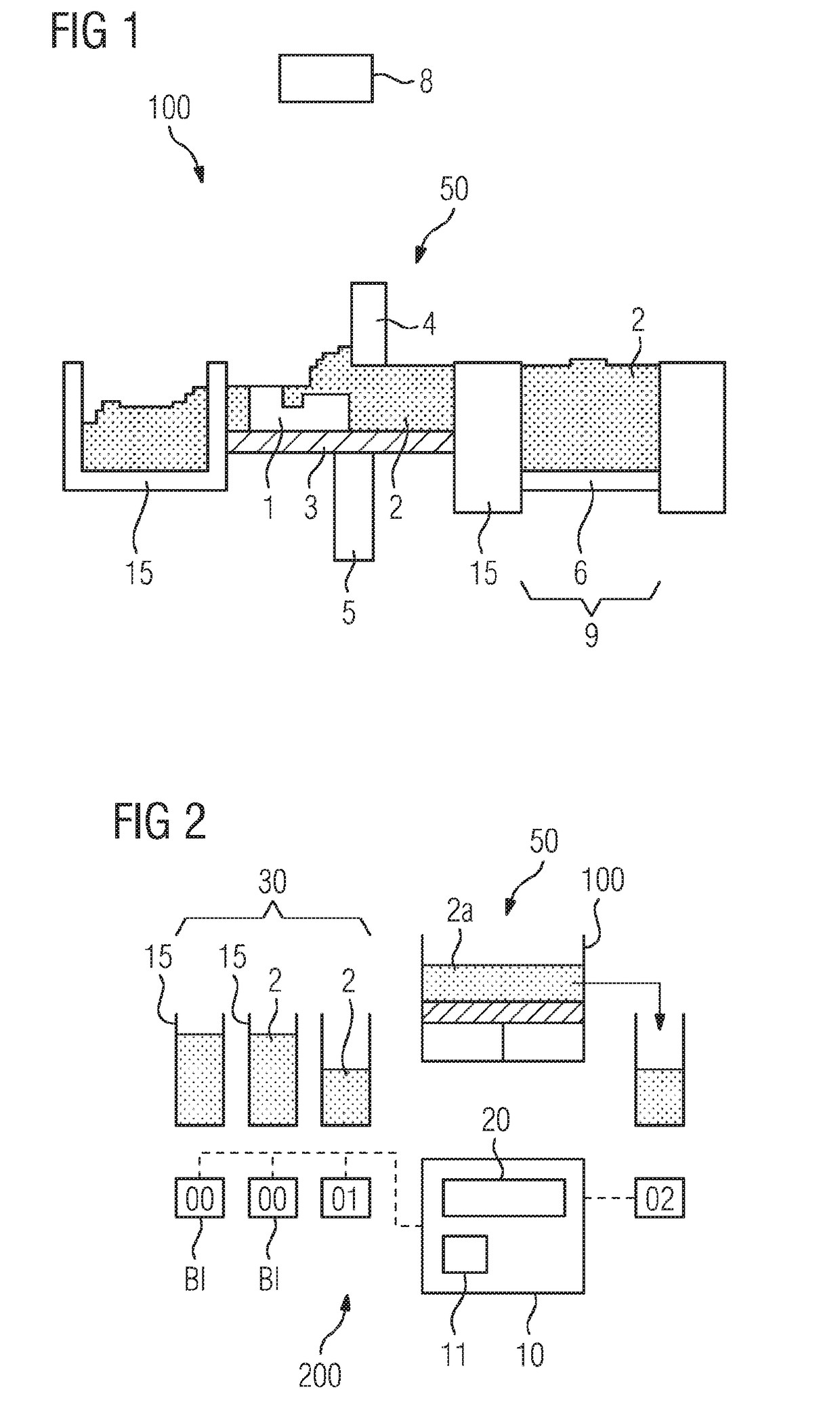
[0046]FIG. 1 shows a schematic of a manufacturing system 100. The manufacturing system 100 is advantageously a system or device for additively manufacturing of a component 1 by means of a powder bed manufacturing process, such as selective laser melting. Alternatively, the manufacturing process may be or comprise selective laser sintering and / or electron beam melting.

[0047]Accordingly, in the manufacturing system 100, the component 1 is advantageously manufactured or build up layerwise. Particularly Selective Laser Melting (SLM) is a advantageous powder-bed additive manufacturing process by which a high power laser can be used to build up a 3D part layer-by-layer for research and / or industrial applications.

[0048]The component 1 may be any user-defined or pre-defined plastic ceramic but advantageously metallic component which is to be additive...


PUM

PropertyMeasurementUnit
Areaaaaaaaaaaa

Abstract

Quality control method and control system for a stock of a base material for the additive manufacture of components includes selecting a batch of a base material out of a plurality of indexed batches of the stock, wherein base material assigned to the same batch index is indicative to the quality of the respective base material, loading a quantity of base material of the selected batch into a manufacturing system, additively manufacturing the component from the base material, wherein the base material of the selected batch is exposed to manufacturing conditions in a build area and updating the batch index of the base material remaining from the additive manufacture in the build area according to the exposure.

Description

CROSS REFERENCE TO RELATED APPLICATIONS[0001]This application is the US National Stage of International Application No. PCT / EP2017 / 052834 filed Feb. 9, 2017, and claims the benefit thereof. The International Application claims the benefit of European Application No. EP16163785 filed Apr. 5, 2016. All of the applications are incorporated by reference herein in their entirety.FIELD OF INVENTION[0002]The present invention relates to a quality control method of a stock of a base material for the additive manufacture of components, advantageously for a plurality of additive manufacturing jobs. Further, the present invention relates to a control system for handling and assuring the quality of a stock of base material and a facility comprising the control system. Still further, the present invention relates to a computer readable medium.BACKGROUND OF INVENTION[0003]Powder bed manufacturing methods such as selective laser melting or selective laser sintering are relatively well known method...

Claims


Application Information

Patent Timeline
IPC IPC(8): B29C64/393B33Y10/00B33Y30/00B33Y50/02B22F3/00B29C64/35B29C64/153B28B1/00B28B17/00B33Y40/00B29C64/20
CPCB29C64/393B33Y10/00B33Y30/00B33Y50/02B22F3/008B29C64/35B29C64/153B28B1/001B28B17/0081B33Y40/00B29C64/20B29C64/386B29C64/357B29C64/259Y02P10/25B22F10/28B22F10/73B22F10/00
Inventor HOCKLEY, CARLLEBED, YAROSLAV
Owner SIEMENS ENERGY GLOBAL GMBH & CO KG
Learn More