Device, system, and method for cleaning the interior of the tubes in air-cooled heat exchangers

a technology of air-cooled heat exchangers and cleaning devices, which is applied in the direction of flush cleaning, lighting and heating apparatus, manufacturing tools, etc., can solve the problems that none of them disclose the use of electromagnetically attached and positioned grit-resistant nozzles to clean such tubes using high pressure air and finely divided abrasives. , to achieve the effect of safe, efficient, economical and environmental protection

Active Publication Date: 2019-02-07
CURRAN EDWARD LAWRENCE +1
View PDF0 Cites 4 Cited by
  • Summary
  • Abstract
  • Description
  • Claims
  • Application Information

AI Technical Summary

Benefits of technology

This patent describes a device, system, and method for safely and efficiently cleaning the inside of tubes in air-cooled heat exchangers. The device uses high-pressure air with tiny abrasive particles to remove any waste buildup. It captures the spent abrasive and removed fouling material and separates it from the waste air before releasing it into the atmosphere. The device also includes a device that allows workers to easily position and secure nozzles for cleaning without having to hold them by hand. Overall, this invention enhances safety for workers while maintaining efficiency, economy, and environmental protection.

Problems solved by technology

Although U.S. patents and published patent applications are known which disclose various devices, systems, and methods for cleaning the interior of air-cooled heat exchanger tubes, none of them disclose using electromagnetically attached and positioned grit-resistant nozzles to clean such tubes using high pressure air with entrained finely divided abrasive.

Method used


Image

  • Device, system, and method for cleaning the interior of the tubes in air-cooled heat exchangers
  • Device, system, and method for cleaning the interior of the tubes in air-cooled heat exchangers
  • Device, system, and method for cleaning the interior of the tubes in air-cooled heat exchangers

Examples


Embodiment Construction

[0055]1. Detailed Description of the Preferred Embodiment of the Electromagnetic Nozzle Support

[0056]An electromagnetic nozzle support is disclosed in detail that alleviates the need for inlet technician 606 and outlet technician 620 to manually hold their grit-resistant nozzles 106 and nozzle holders 108 against the tube ends during cleaning.

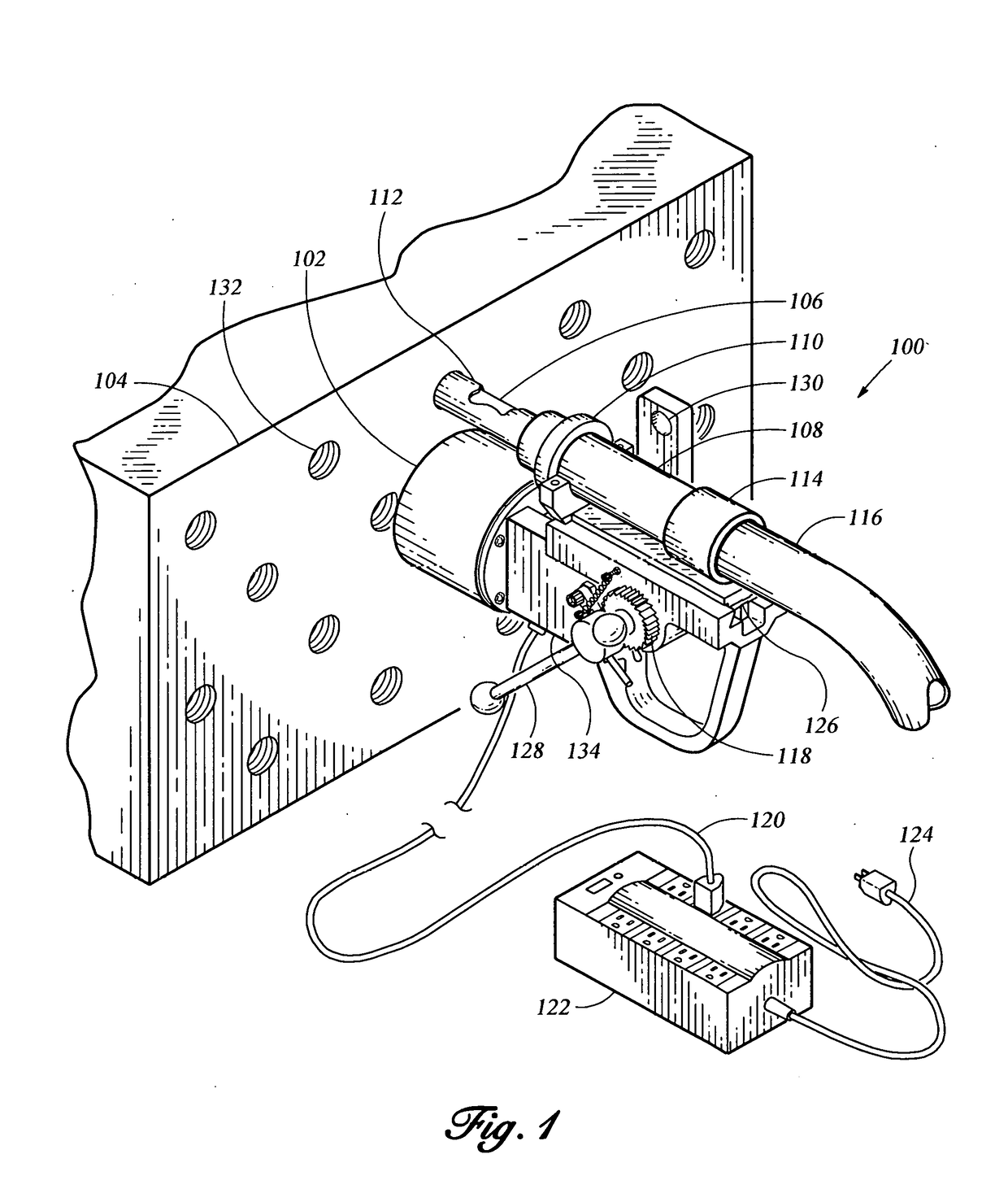
[0057]100 in FIG. 1 points to the electromagnetic nozzle support in place for cleaning one of several ferromagnetic tubes. The electromagnetic nozzle support comprises a portable electromagnetic drill guide 134, here a Kanetec® Magbore Model KCD-MN1-MWK1, manufactured and sold by Kanetec USA Corporation, but the invention may be practiced with another manufacturer's portable electromagnetic drill guide. FIG. 1 shows the features of Item 134 required to practice the invention. Item 102 is an electromagnet energized by single-phase 120 VAC power. It has a nominal holding force of 700 to 800 lbs. Item 126 is a rack and pinion to move the drill gui...


PUM


Abstract

A device, system, and method is disclosed for cleaning the interior of the tubes in air-cooled heat exchangers. The tubes are cleaned using dry finely divided abrasive entrained in high pressure air blasted through the tube to remove any accumulation in the tube or on the tube walls resulting in a bright metal condition suitable for inspection by the Internal Rotary Inspection System, or application of a corrosion-resistant coating, or a lesser level of cleanliness appropriate for return to service. The device is electromagnetically attached to the outside of a ferromagnetic tube header, or to a ferromagnetic plate secured to the outside of a non-ferromagnetic plug-type header or a plate-type header of any material, to temporarily secure a grit-resistant nozzle assembly and position the nozzle for proper application of the high pressure air and entrained abrasive to facilitate cleaning, avoid tube damage, and provide for operator safety. The disclosure still further relates to a system and a method, both employing the device, to clean the interior of the tubes with dry abrasive blasting using high pressure air, and at the other end of the tube, capturing the air, spent abrasive, and material removed from the tube, separating the spent abrasive and removed material from the waste air, filtering the waste air, and exhausting the now filtered air to the environment; all without fugitive emissions.

Description

CROSS-REFERENCES RELATED APPLICATIONS[0001]Not applicable.STATEMENT REGARDING FEDERALLY SPONSORED RESEARCH OR DEVELOPMENT[0002]Not applicable.NAMES OF THE PARTIES TO A JOINT RESEARCH AGREEMENT[0003]Not applicable.REFERENCE TO A “SEQUENCE LISTING.”[0004]Not applicable.STATEMENT REGARDING PRIOR DISCLOSURES BY THE INVENTOR OR A JOINT INVENTOR[0005]Not applicable.BACKGROUND OF THE INVENTIONField of the Invention[0006]This invention relates to a device, system, and method for cleaning the interior of the tubes in air-cooled heat exchangers.[0007]This invention further relates to a cleaning method that uses dry abrasive blasted through the tube using high pressure air to remove any accumulation in the tube or on the tube walls resulting in a bright metal finish suitable for inspection or coating or a predetermined level of cleanliness for return to service.[0008]This invention still further relates to a device that is electromagnetically secured to the outside of a tube header to temporar...

Claims


Application Information

Patent Timeline
IPC IPC(8): B24C3/32B24C5/04B24C7/00F28G1/16F28G9/00F28G15/04
CPCB24C3/325B24C5/04B24C7/0046F28G1/163F28G9/00F28G15/04F28G1/12B24C3/327
Inventor CURRAN, EDWARD LAWRENCEKOLMAN, JASON FARRELL
Owner CURRAN EDWARD LAWRENCE
Why Eureka
Try Eureka