Assay device

a technology of assay device and liquid sample, which is applied in the field of assay device, can solve the problems of reducing the accuracy of test, and requiring additional expense for the use of inorganic optoelectrical components, so as to achieve the effect of improving the accuracy of the resulting indication of the analyte concentration in the liquid sample, reducing the sensitivity or specificity of lfd measurements, and compact arrangemen

Inactive Publication Date: 2019-01-31
CAMBRIDGE DISPLAY TECH LTD
View PDF0 Cites 0 Cited by
  • Summary
  • Abstract
  • Description
  • Claims
  • Application Information

AI Technical Summary

Benefits of technology

[0108]FIG. 12 illustrates a 1-row pixel pattern of an embodiment of an assay device according to the present invention. The reference line 14, reaction lines 8 and 12, and control line 13 are provided on the lateral flow membrane. The OLED and OPD production processes allow pixels of any size and positioning to be created to overlay the reaction and control lines. In FIG. 12, the pixel outlines 25, 26, and 27 shown as dashed lines represent the outline of the OPD sensitive regions and OLED pixels. These pixels are centred on the reaction lines 8, 12 (or control line 13). The pixel outlines 25, 26, and 27 are also smaller than the reaction lines 8, 12 (or control line 13). In this way, the light which enters the OPD from the OLED without passing through the reaction line (i.e. passing through a part of the lateral flow membrane not forming part of the reaction line or control line) is minimised and / or substantially eliminated. In some embodiments, the pixel outlines may have substantially the same extent as the reaction lines. The reaction lines 8, 12 may be correspond to assays for the same analyte. In this way, the accuracy of any resulting indications of the analyte concentration in the liquid sample can be maximised by multiple assays of the same sample.
[0109]FIG. 13 illustrates a 2-row pixel pattern of an embodiment of an assay device according to the present invention. In this embodiment, there are two parallel lateral flow membranes. As described previously, the reference line 14 is used to align the reaction regions 28, 29, 30, 31, 32, 33 with the OPD and OLED outlines 34, 35, 36, 37, 38, 39 respectively. By diagonally offsetting the matched reaction regions (lines) from each other, the light bleed between two neighbouring reaction regions, is minimised. In this way, for example, the amount of light from the OPD / OLED outline 37 detectable by the OPD on the OPD / OLED outline 34, 35 is minimised. This allows a particularly compact arrangement of assays in a single assay device. In some embodiments, each parallel lateral flow membrane can contain a single reaction region, with each lateral flow membrane testing for a different analyte. In other embodiments, each parallel lateral flow membrane can contain a single or multiple reaction regions, with each lateral flow membrane testing for the same one or group of analytes. This allows the accuracy of the resulting indications of the analyte concentrations in the liquid sample to be improved. In yet other embodiments, multiple testing regions on a plurality of parallel lateral flow membranes can be used to test for the same analyte in different ways. In this way, one lateral flow membrane may test for a given analyte using a sandwich assay technique, whilst another lateral flow membrane may test for the same given analyte using a competitive assay technique.
[0110]FIGS. 14 and 15 illustrate respectively a 3-row and 4-row pixel pattern of an embodiment of an assay device according to the present invention. The reaction regions 140, 142 provided on the lateral flow membrane are arranged to minimise light from the OLED having outline 141, 143 bleeding into the outline of any neighbouring OPD having outline 141, 143. As before, the reference line 14 is provided for alignment purposes.
[0111]Whilst in the embodiments shown, the reaction lines and / or reaction regions are intended to extend to each side of each lateral flow membrane, as seen specifically in reaction line 12, the invention extends to alternative embodiments where the reaction lines and / or reaction regions do not extend to each side of each lateral flow membrane. For example, the reaction regions may be centred in the middle of the lateral flow membrane. Alternatively, two distinct regions may be provided side-by-side on a lateral flow membrane. There may be a space on the lateral flow membrane between the two reaction regions. In some embodiments, the two reaction regions are provided in contact with each other. In some embodiments, two or more regions may be spaced or offset both in the proximal-distal direction, and in the width direction of the lateral flow membrane. The reaction regions may be provided on distinct lateral flow membranes which may be provided, for example, side-by-side.
[0112]Whilst embodiments of the present invention have been described using direct tagging, indirect tagging is also possible. In embodiments where a first antibody binds to the analyte, the tagging particle may be bound to a further antibody, which is configured to bind to the first antibody. In this way the same labelled antibody can be used for several different analytes.
[0113]Whilst the embodiments shown use a conjugate pad, it will be appreciated that the sample may be pre-treated with the analyte tags. This may ensure better mixing and binding between the analyte and analyte tags, particularly where there are very low concentrations of analyte. In this case, the conjugate pad is not required, and the pre-treated sample may be deposited on the sample pad or the lateral flow membrane directly. In some embodiments where the presence or concentration of multiple analytes is to be tested, the sample may be pre-treated for only some of the analytes of interest. In this case, a conjugate pad is still required.

Problems solved by technology

The use of inorganic optoelectrical components may therefore necessitate additional expense, bulk, and decreased portability associated with these additional optical components.
Such stray-light creates “cross-talk” between detectors that reduces the sensitivity or specificity of LFD measurements and reduces the accuracy of the test results.

Method used


Image

  • Assay device
  • Assay device
  • Assay device

Examples


example 1

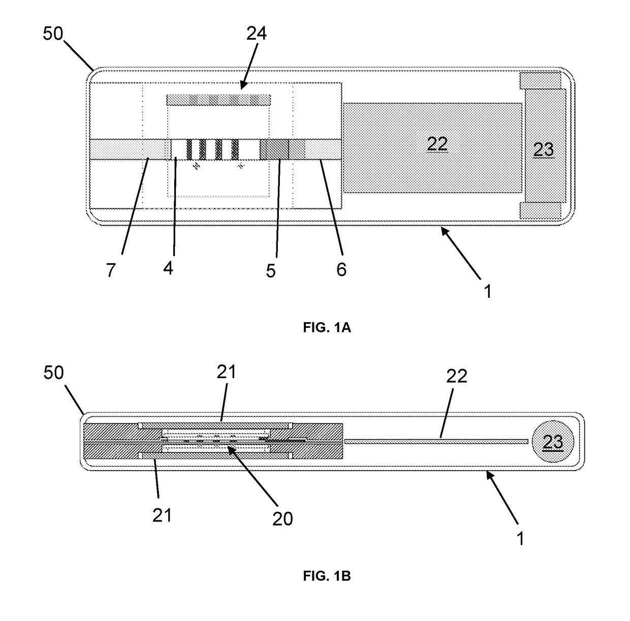
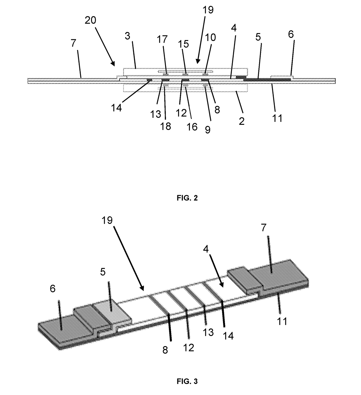
[0116]A device comprising seven groups otherwise substantially as shown in FIGS. 1 and 2 was provided in which the OLED detectors were manufactured using solution processing and had the following structure:

glass / ITO / hole injection layer / polymer host+Ir-dendrimer green emitter / Ag

FIG. 7 shows the angular dependence of the emission profile of the OLED emitter (broken line) compared with Lambertian emission (solid line), showing that emission is near-Lambertian. The OPD detectors were also manufactured using solution processing and had the following structure:

glass / ITO / hole transporting layer / polymer donor+acceptor / Ag

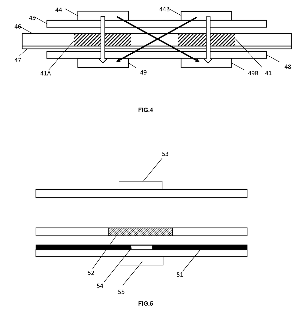
A mask was disposed between the OLED substrate and the membrane support and the separation between them was about 0.2 mm. The OPD substrate was about 1.0 mm from the wet nitrocellulose membrane that was devoid of tagging particles. The OLED and OPD pixel sizes were 0.5 mm×2 mm, groups were spaced apart by 2 mm, and the mask aperture size was 0.5 mm×2.4 mm. The cross-talk (C...

example 2

[0117]A device otherwise substantially as in Example 1 is provided in which the OLED emitters further comprise a distributed Bragg reflector positioned between the ITO and substrate and having the structure:

[ITO, 50 nm] / TiO2, 56 nm / SiO2, 92 nm / TiO2, 56 nm / SiO2, 92 nm / TiO2, 56 nm / [glass]

and the device comprises 21 groups. The OLEDs exhibit substantially sub-Lambertian emission. The cross-talk (C) between at least two groups is at least 30 dB.

example 3

[0118]A device otherwise substantially as in Example 1 is provided in which the OLED emitters are top emitting OLEDs comprising a strong microcavity and have the structure:

glass / Ag, 85 nm / hole transporting layer / polymer donor+acceptor / Ag, TeO2, 10 nm

and the spacing between electrodes is about 250 nm. In this embodiment, the OLEDs are positioned on the side of the substrate nearer to the membrane as these OLEDs are top-emitting.

The device comprises 21 groups and the OLEDs exhibit substantially sub-Lambertian emission. The cross-talk (C) between at least two groups is at least 40 dB.


PUM

PropertyMeasurementUnit
concentrationaaaaaaaaaa
photocurrentaaaaaaaaaa
fluorescenceaaaaaaaaaa

Abstract

An assay device for the quantitative determination of the concentration of at least one analyte in a liquid sample. The device comprises a lateral flow membrane (46) comprising a plurality of test regions (41A, 41B) and formed from a light transmissive material, a plurality (44A, 44B) of planar organic light emitting diode (OLED) emitters comprising an emission layer of an organic electroluminescent material, and a plurality (49A, 49B) of planar organic photodetectors (OPDs) comprising an absorption layer of an organic photovoltaic material. Each test region comprises an immobilised component for retaining analyte tagging particles. Each test region is aligned with the emission layer of one emitter and the absorption layer of one photodetector. The aligned emitter, photodetector, and test region form a group such that the emitter is capable of illuminating the test region and the photodetector is capable of detecting light from the test region. For each group, under conditions where the test region is wet and devoid of tagging particles the energised photodetector photocurrent that is produced is denoted i1, when the group emitter is the only emitter that is energised, and T2 when the emitter of another group is additionally energised. Cross-talk (C), is then represented by the black arrows, and is defined according to the equation: C=20 log10 (i1/(i2−i1)) C is arranged to be greater than about 20 dB for at least one group of the device.

Description

[0001]The present invention relates to an improved assay device for the quantitative determination of the concentration of at least one analyte in a liquid sample. The liquid sample may be an original biological sample, e.g. plasma, serum, urine or saliva, or a biological sample reduced to a liquid, e.g. a plant or tissue extract.BACKGROUND[0002]Chromatographic-based assay devices such as lateral flow devices (LFDs) have considerable use. One application is in devices that analyse a liquid sample to determine the presence or absence of one or more target analytes. In such devices, there may be a threshold concentration that, when exceeded, produces a qualitative indication that the analyte is present.[0003]LFDs may also provide a quantitative indication of analyte concentration in a sample. Such devices may comprise optical measuring components to quantify a colorimetric reaction or binding event, e.g. the binding of a dye-labelled antibody / analyte complex to a second antibody immob...

Claims


Application Information

Patent Timeline
Patent Type & Authority Applications(United States)
IPC IPC(8): G01N21/84B01L3/00G01N33/558G01N21/64
CPCG01N21/8483B01L3/5023G01N33/558G01N21/6428G01N21/6454B01L2300/0654B01L2300/0825B01L2300/0887B01L2400/0406G01N2021/6439B01L2300/0636G01N2201/0221G01N21/77G01N33/53B01L2300/12G01N33/54388
Inventor HAND, CHRISHOFMANN, OLIVERRYU, GIHANRAMON, MIGUELBENZIE, PHILIPKAY, CHRISTOPHER JOHN
Owner CAMBRIDGE DISPLAY TECH LTD
Why Eureka
Try Eureka