
Configuration of the intensity of the light sources composing a lighting system

a technology of lighting system and intensity, applied in the field of lighting system, can solve the problems of inability to configure the intensity of light sources composing the lighting system, inability to provide a reference spectrum, incomplete choice,

Active Publication Date: 2019-01-17
WATTLUX
View PDF0 Cites 0 Cited by
  • Summary
  • Abstract
  • Description
  • Claims
  • Application Information

AI Technical Summary

Benefits of technology

The technical effect of this patent is to provide a method for configuring a lighting system that can control the light spectrum by combining different sources in a way that results in the desired reference spectrum or its equivalent. This helps to mitigate the disadvantages of current lighting systems.

Problems solved by technology

These existing sources offer a large choice to users, but the choice is incomplete because there is no guarantee that there is a light source available on the market for a given reference spectrum.
Furthermore, these light sources are static and cannot be configured to provide a reference spectrum.
Light sources can achieve high CRI values, but not using all technologies.
Furthermore, if a third light source is present, it is no longer possible to adapt the principal light source to obtain a global spectrum with a sufficiently high CRI.

Method used


Image

  • Configuration of the intensity of the light sources composing a lighting system
  • Configuration of the intensity of the light sources composing a lighting system

Examples


first embodiment

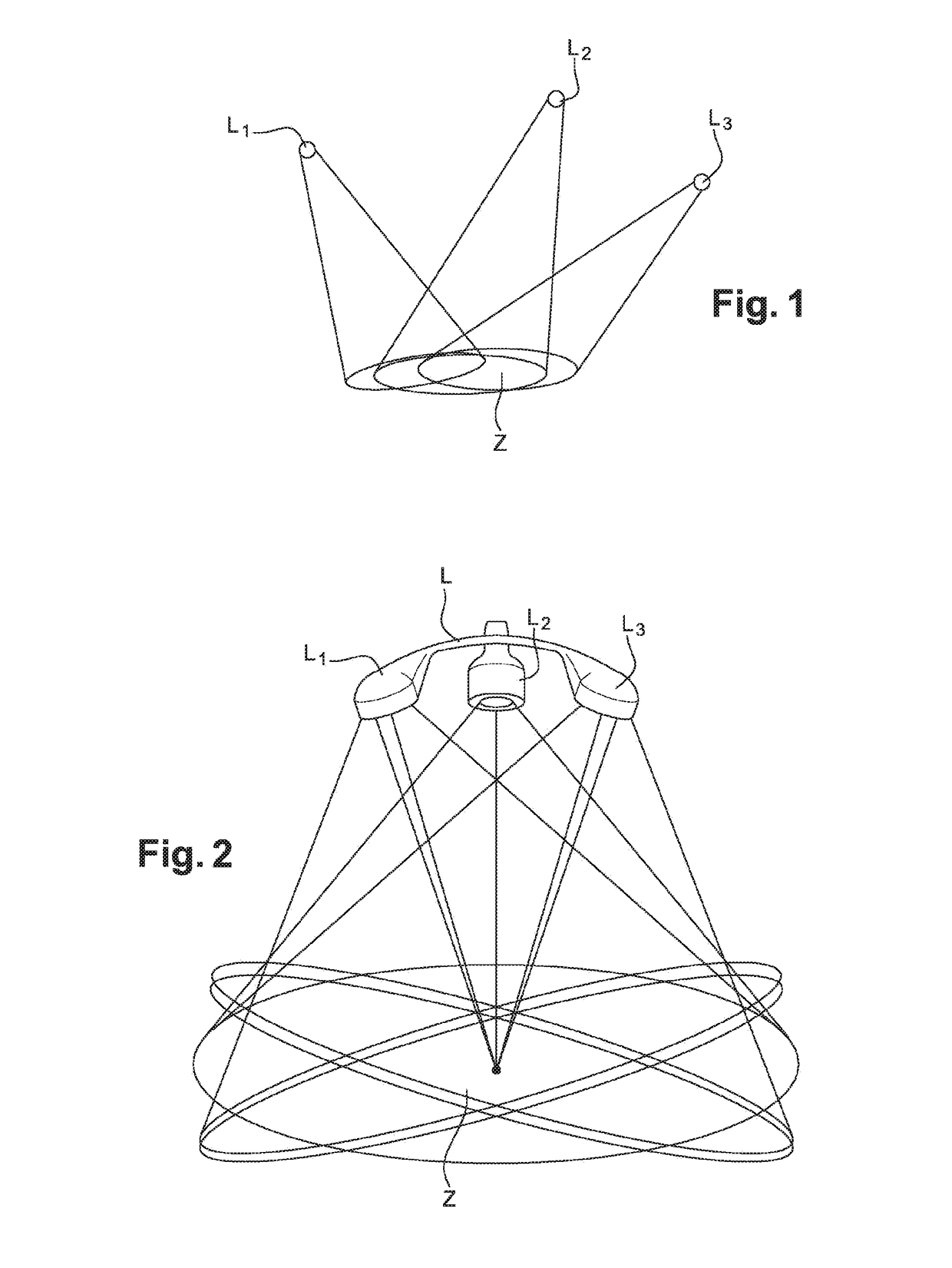
[0032]FIG. 1 illustrates a first embodiment that consists of arranging independent light sources L1, L2, L3, distributed in space (for example in a room) in which the beams are oriented so as to create an overlap zone Z within which the light spectrum is closest to the reference spectrum.

second embodiment

[0033]FIG. 2 illustrates a second embodiment in which the lighting system is composed of a rigid or non-rigid structure L that fixes the different light sources L1, L2, L3 relative to each other. The structure L orients the light beams of each source so as to create the largest possible overlap zone Z within which the light spectrum is closest to the reference spectrum.

[0034]In another embodiment, the light sources are combined inside a single bulb. The overlap zone of the different sources is then very large.

[0035]Different technologies can be used to implement the light sources. In particular, Light Emitting Diodes (LEDs) may be used.

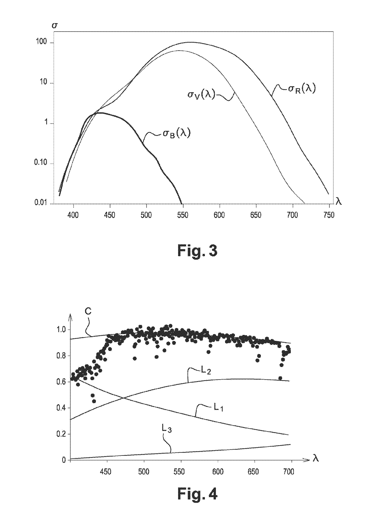
[0036]Each light source Li can be characterised by an intensity φi and a spectrum Si(λ), in which λ represents the wavelength.

[0037]Thus, the synthetic spectrum Ss(λ) of a lighting system composed of n light sources L1, L2, L3, . . . Li, . . . Ln, can be written as the sum of the spectra Si(λ) of each of these sources, weighted by their intensities φi...


PUM


Abstract

The invention relates to a method for configuring a lighting system including a set of at least 3 light sources (Li) having different spectra (Si(λ)), including a step of automatically defining the intensities (φi) of each of the light sources of said set by minimising a distance between a reference spectrum (SR(λ)) and a synthetic spectrum (Ss(λ)) defined by the sum of the spectra (Si(λ)) of each source (Li) of said set weighted by said intensities (φi).

Description

DOMAIN OF THE INVENTION[0001]The invention relates to a lighting system composed of several different light sources. More particularly, it relates to the configuration of the intensity of each of these sources so as to approach a perceived reference spectrum.CONTEXT OF THE INVENTION[0002]There are many light sources available on the market. Each is characterised by a light source and a light spectrum, very often modelled by its colour temperature with reference to a black body heated to between 1500 and 10000 K that would provide an emission spectrum in the visible light range similar to that of a light bulb.[0003]These existing sources offer a large choice to users, but the choice is incomplete because there is no guarantee that there is a light source available on the market for a given reference spectrum. Furthermore, these light sources are static and cannot be configured to provide a reference spectrum. A fortiori, it is impossible to take an ambient colorimetric context into a...

Claims


Application Information

Patent Timeline
IPC IPC(8): H05B33/08H05B44/00
CPCH05B33/0866H05B33/086H05B45/20H05B45/24
Inventor BELIN, PATRICKBAILLY, YANNICK
Owner WATTLUX
Learn More